Edit
Fillet
|
|
*Modify toolbar |
| Modify menu > Elements > Fillet |
This function rounds line or wall corners (in ELITECAD Architecture). Joints, which have already been rounded, can be modified or restored to a corner. After entering the desired radius, you must click INSIDE the filleted corner.
Fillet property bar

Fillet
![]()
The symbol indicates that the FILLET function is active. You can switch to CHAMFER or NOTCH here.
Radius
![]()
Enter the radius to be used for the fillet operation.
Modify
![]()
This function modifies or deletes previously defined fillets. Enter a "0" in order to delete a fillet.
Tip
More corners with the same radius are filleted when you indicate more points.
T-joints with these functions are also editable. The function affects the entire picture and not just the active object.
Notch
|
|
*Modify toolbar > Fillet > property bar |
| Modify menu > Elements > Fillet |
This function generates a notch in the corner of two lines or it is used to modify existing notches. After entering the desired radius, you must click INSIDE the corner. The notch is generated automatically.
Notch property bar

The functions on the property bar are identical to the FILLET function.
Chamfer
|
|
*Modify toolbar |
| Modify menu > Elements > Chamfer |
This function generates a chamfer in the corner of two lines or walls (in ELITECAD Architecture) by specifying the chamfer angle and distance or the function is used to modify existing fillets. The chamfer angle and distance ("0" if the fillets are symmetrical) can be specified. The point of both lines will subsequently be marked by the crosshair, which will need to be moved closer to the line, and which is then used as a reference for the angle and parallel distance.
Chamfer property bar

Chamfer
![]()
The symbol indicates that the CHAMFER function is active. You can switch to FILLET or NOTCH here.
Chamfer type
There are three options to define a chamfer.
![]()
![]()
![]()
Chamfer by two distances
![]()
![]()
![]()
This option defines a chamfer by two distances measured from the corner.
Chamfer by distance and angle
![]()
![]()
![]()
This option defines a chamfer by a distance and an angle.
Chamfer symmetrically by distance
![]()
![]()
This option uses two symmetrical distances from the corner point to define the chamfer.
Modify
![]()
This function modifies or deletes a previously defined chamfer. In order to delete a fillet, switch to "symmetrically by distance" and enter "0".
Tip
The function is only applicable to straight lines (not curves). Both lines can represent different models. More identical fillets are created by specifying more points. Should the fillets need modifying, this can be done by entering "0". The active values of displayed fillets are taken into account when the entry for the angle or distance (value maintained) is changed to "-1". It is then possible that, for example, multiple fillets with different angles the same fillet distances apart and vice versa can be modified. A change in angle and distance for existing fillets is also possible.
Divide element
|
|
*Modify toolbar |
| Modify menu > Elements > Divide element |
Divide an element to a particular location. This can be applied to lines, polygons or rectangles.
Join element
|
|
*Modify toolbar |
| Modify menu > Elements > Join element |
Connect adjacent elements lying on a straight line. Only one line needs to be selected. The system combines all possible lines to one line.
Name element
|
|
Elements toolbar |
| Modify menu > Elements > Name element |
This function allows assigning names to elements.
An element has to be selected.
Element names are assigned by functions or by external programs. Used element are described in the corresponding documentation.
Pen/line type of element
|
|
Elements toolbar |
| Modify menu > Elements > Modify pen/line type of element |
This applies to an element's pen and line type settings. These settings become active when a drawing function is called up (line, rectangle, circle ...).
Modify pen/line type of segment
|
|
Elements toolbar |
| Modify menu > Elements > Pen/line type of segments |
This enables changes to a segment's pen and line type settings (segment = part of an element). Multiple segments can be selected until the function is exited. The chosen segment is separated from the line and remains as a separate line.
Note
Intersection points with geometric lines are not taken into account.
Modify pen/line type of element
|
|
Elements toolbar |
| Modify menu > Elements > Modify pen/line type of element |
This enables changes to an element's pen and line type settings. Multiple segments can be selected until the function is exited.
Globally modify pen/line type of elements
|
|
Elements toolbar |
| Modify menu > Elements > Globally modify pen/line type of elements |
This function allows you to globally modify elements of a desired pen/line type by choosing the pen and line type in the active image.
After activating the function, a query dialog appears with a selection of elements for pen and line type where the individual values are entered and separated by commas. The pen/line type, which should modify the elements, is then entered.
To change elements with pen 1 and line type 1 to pen 3 and line type 4, enter "1.1" to select them and "3.4" for the new pen and line type.
Modify pen/line type of elements from a selection
|
|
Elements toolbar |
| Modify menu > Elements > Modify pen/line of selection |
This function allows you to modify the pen number and line type of a previously drawn element from a selection.
After activating the function, both the pen number and line type, to be changed, are entered. The new pen number and line type are then entered.
Delete element
|
|
Elements toolbar |
This function deletes an element.
Tip
You can also delete an element by directly clicking on it or by selecting it from the selection mode "element/part", and then pressing the Del key. Depending on the settings under OPTIONS, a confirmation prompt appears.
Delete segment
|
|
*Manipulate toolbar; Elements |
This function deletes part of an element. The part needs to be marked off with another element (line or circle).
Delete polygon
|
|
*Manipulate toolbar |
This function deletes an entire sequence of lines.
Delete last drawn element
|
|
*Manipulate toolbar |
This function deletes the last line drawn. When drawing a line, it is preferable to use this function if a point is incorrectly set and you wish to go back without ending the drawing.
Tip
Alternatively, the UNDO function Ctrl + Z can be used.
Delete block
|
|
*Manipulate toolbar |
This function deletes all parts, which lie completely within a determinable polygon.
Tip
If 3D objects are partly inside a polygon, a message appears saying that parameterised objects have been found in the block. In this case, the polygon must be drawn differently or you can remove the object lock under SETTINGS > OPTIONS > WORK PARAMETERS > EDIT (a conversion from the V11 user interface).
Delete section
|
|
*Manipulate toolbar |
This function deletes all parts, which lie within a determinable polygon. Elements or hatches are cut.
Tip
If 3D objects are partly inside a polygon, a message appears saying that parameterised objects have been found in the block. In this case, the polygon must be drawn differently or you can remove the object lock under SETTINGS > OPTIONS > WORK PARAMETERS > EDIT (a conversion from the V11 user interface).
Delete double line
|
|
Special functions toolbar |
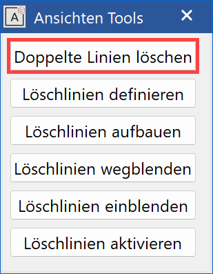
| Extras menu > View tools/deletion lines |
This function is only available in ELITECAD Architecture.
This function eliminates superimposed lines with the same stroke thickness.
Verify 2D model
|
|
Information toolbar |
| Information menu > Verify 2D model |
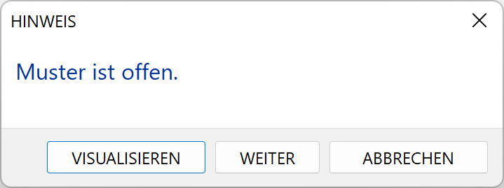
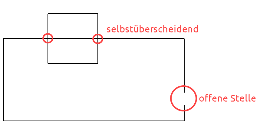
It only makes sense to use this function when you are working with the classification structure (model). This function checks whether the model is a closed contour. A query dialog appears in an open model asking whether it should visualise where the contour is open. The crosshair is set at the open location.
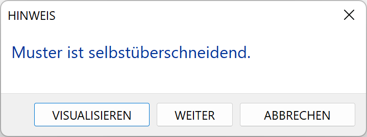
Secondly, the model is checked to see if the model's lines cross each other. These locations can also be highlighted.
Stretch single point
|
|
Elements toolbar |
| Modify menu > Elements > Stretch single point |
This function enables you to stretch or compress an element by moving a boundary point.
After activating the function, you are prompted to specify the point to be moved. You are then prompted to indicate the new position. The element concerned is subsequently moved towards the new point by the distance between the two points and is "stretched" or "compressed" accordingly.
Tip
The same can be achieved by clicking on element and using the handles to manipulate it.
Stretch selected points
|
|
Elements toolbar |
| Modify menu > Elements > Stretch selected points |
This function enables you to stretch or compress one or all combined elements in a point by moving a boundary point.
After activating the function, you are prompted to specify the point to be moved. You are then prompted to indicate the new position. The elements, which should be stretched / compressed, can now be accessed. These are moved towards the new point by the distance between the two points and are "stretched" or "compressed" accordingly.
Tip
The same can be achieved by clicking on element and using the handles to manipulate it. You can select multiple elements by holding down the Shift key.
Stretch all points
|
|
Elements toolbar |
| Modify menu > Elements > Stretch all points |
This function enables you to stretch or compress all combined elements in a point by moving a boundary point.
After activating the function, you are prompted to specify the point to be moved. You are then prompted to indicate the new position. All elements concerned are subsequently moved towards the new point by the distance between the two points and is "stretched" or "compressed" accordingly.
Tip
The same can be achieved by clicking on element and using the handles to manipulate it. You can select multiple elements by holding down the Shift key.