Elements
Drawing lines
|
|
Draw toolbar |
| Draw menu > Draw line |
Draw single lines from a start point to an end point.
Line property bar

The line type and line colour can be selected from the line property bar.
In ELITECAD Architecture the renovation planning state can be selected.
Line length and line angle also appear when editing. Changes of the length are applied relative to the start point.
Draw polygon
|
|
Draw toolbar |
| Draw menu > Draw |
This is used to draw a continuous line. In order to complete the line, the last point must be selected again. The function remains active and more lines can be drawn. If a line has been completed, a new line can be started by selecting another start point. Press the Esc key or click the  function in order to end this function.
A polygon can be selected with a single click. If the Selection mode element part is active, single elements can be accessed.
Polygon property bar

The line type and line colour can be selected from the line property bar.
In ELITECAD Architecture the renovation planning state can be selected.
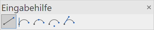
Tip
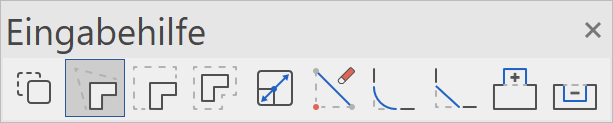
The program shows the additional functions, which are useful when drawing in the input assistant. The functions can be displayed either in a separate input assistant toolbar or on the cursor by pressing the ++tab++ key.
Invert line direction
![]()
The drawing direction is defined by the start and end point of a polygon. The direction can be used to define the start point for the line type.
Polygon via entry of coordinates
Very often it is not possible to capture a point, a certain line length is predefined. These lines can, of course, be constructed with help lines, but it is much easier and more efficient to enter a polygon using coordinates.
Values field
Lengths can be entered directly in the values field. To move to the values field, press the Tab key. In the values field the x value (horizontal), the y value (vertical), the direct value or the angle can be entered.
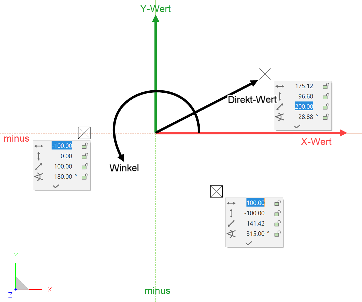
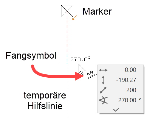
Value on element or help line
If, when a value is entered, the cursor is on an element or a help line that passes through the marker or a temporary reference point, the entry switches to the direct value and you need only enter the distance, without worrying about the angle or the minus range.
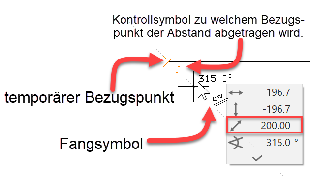
x, y distance from a given point
(Snapmode to-auto
The capture mode to AUTOcapture is directly integrated into the AUTOcapture mode. If, when a value is entered, the cursor is on a point, the values of this point are removed. The sign for the direction must be taken into consideration.


Manipulate Polygon
A created polygon can be modified. The first click on the polygon selects it and the handles appear at the corners.
| Polygon | 1st click | 1st click effect | 2. click |
|---|---|---|---|
 |
 |
 |
 |
The second click decides which corner or which edge to modify. So that you can tell that the cursor is over a changeable element, it changes its appearance to a quadruple arrow.
Other manipulation functions appear depending on whether a line, a curve, a corner or an end point was clicked. The function last selected is immediately active.
The available manipulation options can be displayed in a separate input assistant toolbar either by pressing the Tab key or on the cursor.
Manipulation options on a corner
| Stretch point | Delete point |
|---|---|
 |
 |
| Chamfer | Fillet |
 |
 |
Manipulation options on an edge
| Insert point | Round edge | Stretch element |
|---|---|---|
 |
 |
 |
Manipulation options for a corner or edge
| Move selection | Scale element |
|---|---|
 |
 |
By pressing the Ctrl key at the same time, the selection can be copied when moved. When scaling, a reference point must be set as the starting point for scaling.
| Move elements parallel | Move all edges parallel |
|---|---|
 |
 |
Selection element part
For certain manipulations such as move selection or extend elements/move in parallel, it makes sense to perform the manipulation not on the entire polygon but only on certain elements.
To enable individual elements to be selected, the selection mode must be switched to Selection element part. Alternatively, press the Alt key. Multiple selection is possible with Shift .

Change polygon
A distinction is made between whether a closed or an open polygon is to be modified.
After selecting the CHANGE function, the drawing functions with which the change can be drawn appear in the input assistant.
Expand/reduce closed polygon by one circle:
First, select the EXPAND OR REDUCE POLYGON function followed by the drawing function CIRCLE.
| Drawing function Extend circle | Polygon | Reduce polygon |
|---|---|---|
 |
 |
 |
Open polygon:
![]()
For the open polygon, the extension polygon must be started on the geometry and ended by double-clicking on the geometry. An exception is when you start on an end point. If the polygon cannot be closed properly, the change is not carried out.
![]()
![]()

Rectangle by diagonal
|
|
Draw toolbar |
| Draw menu > Rectangle by diagonal |
Creating a rectangle by entering two points over a diagonal.
While drawing a rectangle the entry mode can be changed in the input assistant. Three options are available:
![]() Rectangle by diagonal
Rectangle by diagonal
![]() Rectangle by dimensions and reference point
Rectangle by dimensions and reference point
![]() Rectangle by edge and height
Rectangle by edge and height
Rectangle property bar

The line type and line colour can be selected from the property bar.
In ELITECAD Architecture the renovation planning state can be selected.
Rectangle by dimensions and reference point
|
|
Draw toolbar |
| Draw menu > Rectangle by dimension and reference point |
This function enables the drawing of a rectangle by entering its width and height as well as the optional reference point and a display angle.
While drawing a rectangle the entry mode can be changed in the input assistant. Three options are available:
![]() Rectangle by diagonal
Rectangle by diagonal
![]() Rectangle by dimensions and reference point
Rectangle by dimensions and reference point
![]() Rectangle by edge and height
Rectangle by edge and height
Rectangle property bar

The line type, line colour, width, height, angle and reference point can be selected from the property bar.
In ELITECAD Architecture the renovation planning state can be selected.
Regular Polygon
|
|
Elements toolbar |
| Draw menu > Regular polygon |
This function enables the drawing of a closed, regular polygon.

While drawing a regular polygon the entry mode can be changed in the input assistant. Five options are available:
![]() Regular polygon with reference point, radius/edge length and angle
Regular polygon with reference point, radius/edge length and angle
![]() Regular polygon with centre point and corner
Regular polygon with centre point and corner
![]() Regular polygon with centre point and edge-centre point
Regular polygon with centre point and edge-centre point
![]() Regular polygon with two corners
Regular polygon with two corners
![]() Regular polygon with two edge-centre points
Regular polygon with two edge-centre points
Regular Polygon property bar

The line type, line colour, number of corners, edge length, angle position and reference point can be selected from the property bar.
In ELITECAD Architecture the renovation planning state can also be selected.

The lock next to edge length and angle position determines whether the number in the field or the size of the polygon are changed when selecting a different field.
![]() The number field changes and the polygon in the graphics window remains unchanged.
The number field changes and the polygon in the graphics window remains unchanged.
![]() The size of the polygon changes to match the entry type and the entered length remains unchanged.
The size of the polygon changes to match the entry type and the entered length remains unchanged.
Parallel contour
|
|
Draw toolbar |
| Draw menu > Parallel contour |
This function creates a new contour on one side of the original contour (open or closed) which is displaced so that all points are parallel to the desired distance.
After activating the function, enter the contour distance into the property bar. After selecting the contour, the direction of the parallel contour can be selected by flipping. The selected contour is automatically scanned or the points can be marked over a polygonal chain. Closed profiles are automatically recognised, open profiles must be completed by specifying the end point (close polygon).

In ELITECAD Architecture the renovation planning state can be selected.
Double line
|
|
Geometry toolbar |
| Draw menu > Geometry > Double line |
This function enables you to create a double line (e.g. pipe, wall) easily. Only a single line representing either one of the sides or the double line's centre line must be drawn.
Double line property bar

The property bar becomes visible as soon as the DOUBLE LINE function is started.
| Function | Description |
|---|---|
| Line parameters | |
| Renovation planning state | |
| Colour selection perimeter contour | |
| Line type perimeter contour | |
| Colour selection centre line | |
| Width | |
| Closed at start | |
| Closed at end | |
| Corner line | |
| Centre line | |
| Connection open or with pen 0 |
The line is specified by the input of points. The input is completed when the last point is entered twice. The entered line describes either the left or the right side or the centre line.
Depending on the cursor position these options are displayed as a preview and selected by clicking with the mouse button.
Halving of an angle
|
|
Geometry toolbar |
| Draw menu > Geometry > Halving of an angle |
This function enables elements or help lines with half angles to be generated.
After activating the function, a first and a second element are requested. If two help lines are clicked, a help line is generated.
If at least one element is selected, a line with an active pen/line type is drawn and an additional query for the position of the start and end points appears. The suggested position can be confirmed by hitting [Enter] each time or by clicking the specific points with the mouse.