Cam
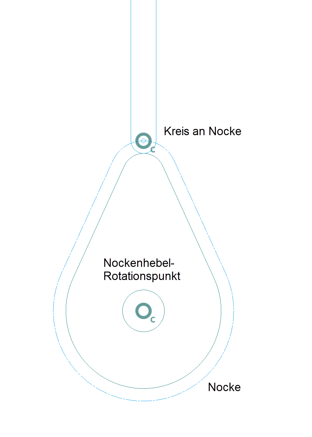
The kinematics system is driven by turning a cam of any contour. The outer contour of the cam must be a closed polygon.
Within the cam rotation point, there must be a circle labelled as the cam drawn. The outer contour and this circle must be separate objects (models). The part (lever) sliding on the cam must have a circle (segment of a circle) which abuts on the cam and which is automatically queried for the designation of the cam rotation point "Which circle is on the cam?". This circle centre automatically generates a parallel contour to the cam with pen / line type 0/8, which is required to determine the position of the lever at different cam positions. (This automatic circle belongs to the object of the cam).
Note
If the cam has a line with pen 0, line type 8, this is automatically defined as the detection contour, and the lever is set on this contour when the cam is rotated.
There are 3 different variants of a system with a cam
Variant 1
The cam is directly connected to the start lever.


Here the starting lever always moves on the line that connects the two centre points of the indicated circles in the starting position.
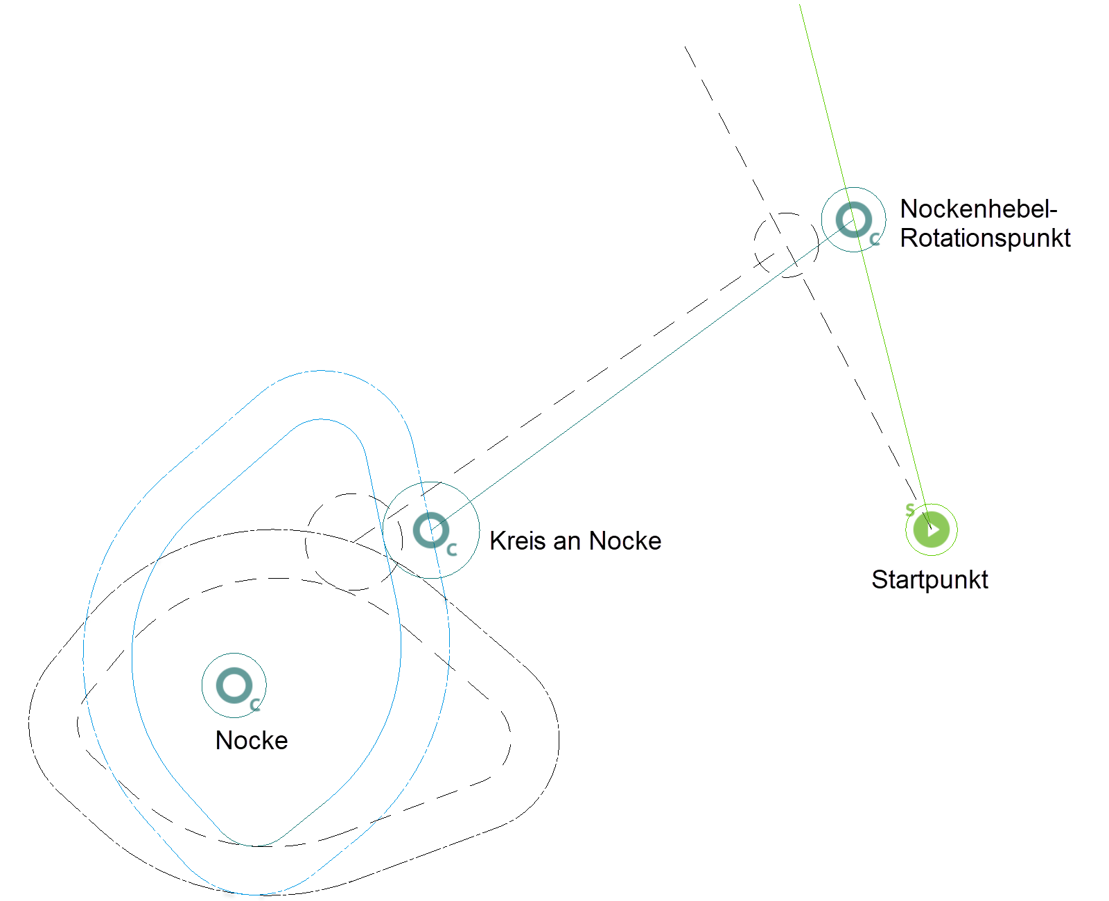
Variant 2
The cam is connected to a lever through the cam lever rotation point with the start lever. This means that the drive lever moves again along the connecting line for the cam and the cam lever rotation point rotates around the starting point.


Additional levers can be attached to the start lever using a rotation point.
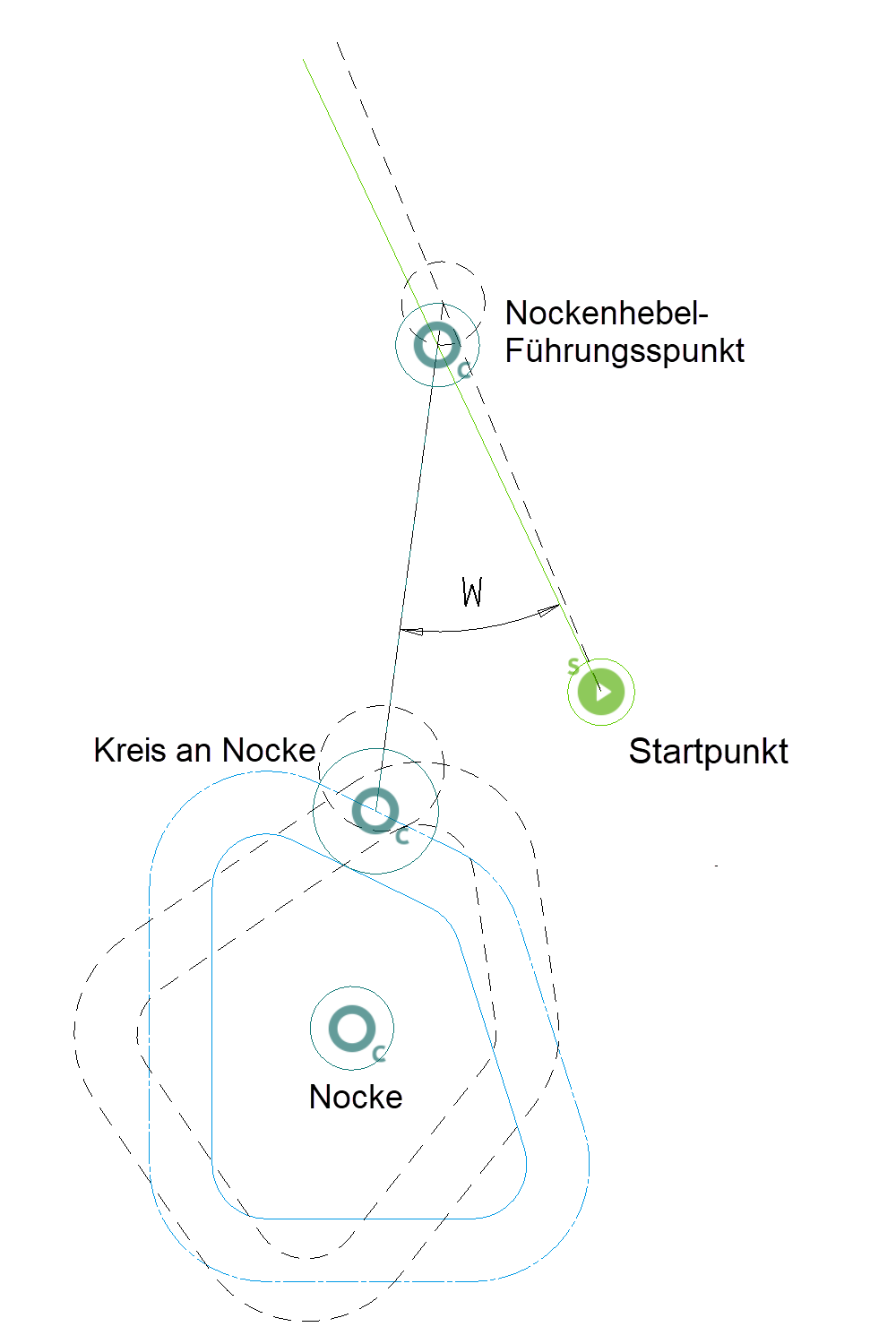
Variant 3
The cam is connected to the start lever by a lever through the cam lever guide point. This means that the drive lever moves again along the connecting line for the cam, whereby the position angle W does not change. The cam lever guide point moves along the start lever and thereby also rotates it around the start point (drive lever guides the start lever).
Sample:


Depiction in colour assignment mode
(colour mode pen)

Additional levers can be attached to the start lever using a rotation point.