Guide
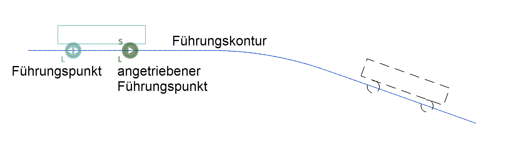
Guide point
![]()
If a circle is referred to as a guide point, the centre point must lie on a guide contour. The guide point only moves along the guide contour if the system is driven by a starting lever.
Each guide point is marked with a symbol that includes an "L" in the preset colour.
Guide contour
![]()
The path of the guide point is defined with the guide contour, whereby the circle centre of the guide point must lie on this contour. The contour must be a separate object (model) and can consist of any number of 2D elements. Straight lines or arcs are allowed for these elements (e.g. also a circle). The length of the guide contour limits the movement of the guide point.
Example crank drive:


Example crank drive with piston:
Other parts can also be attached to the guide point using a rotation point. These attached parts can also use the planned guide contour.

Depiction in colour assignments mode
(colour mode pen)

Driven guide point
![]()
The driven guide point moves either the specified distance along the guide contour or as long as a movement is possible (endless loop). The kinematics system is driven based on this movement.
Each driven guide point is marked with a symbol that includes a "C" in the preset colour.
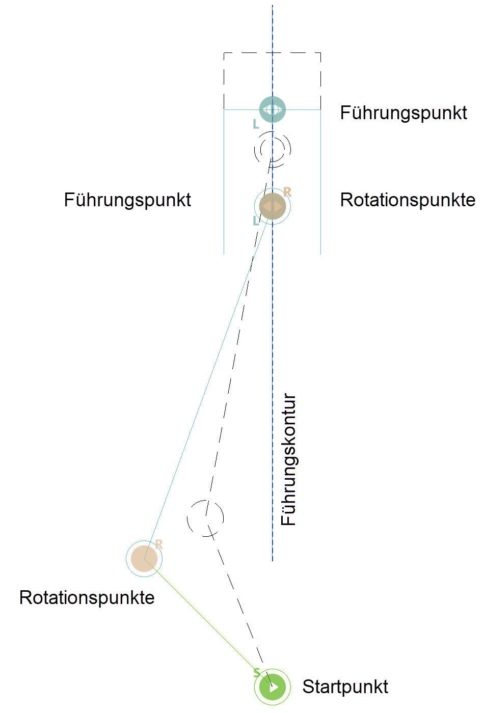
Variant 1:
The lever with the driven guide point must be connected by rotation points to a lever upon which a starting point is defined.
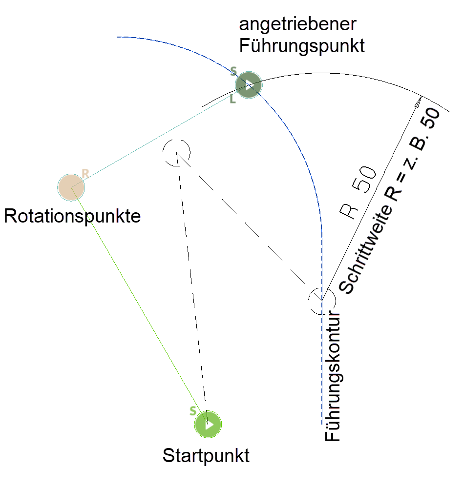
Note
The specified distance for the movement (step size) does not correspond to the actual distance on the guide contour, but a circle with the radius of the step size (centre is the guide point) is cut with the guide contour.
Sample:

Further parts can be attached to the guide point (see example with normal guide point).
Variant 2:
A driven guide point and another guide point are defined on a guide contour. In this case, the system is moved along the guide contour according to the set increment or to the end of the guide contour.

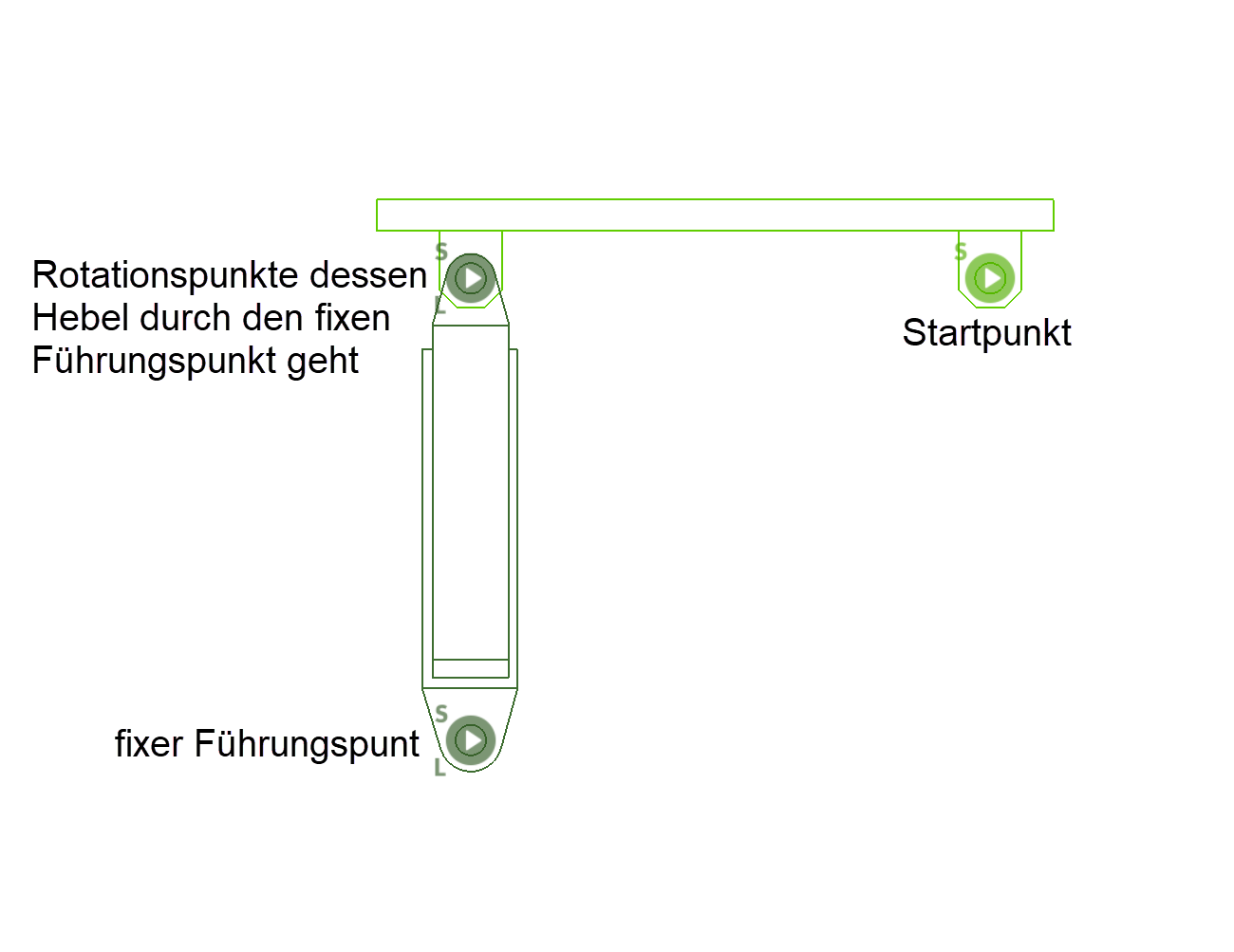
Fixed guide point
![]()
A hydraulic or pneumatic cylinder can be simulated with the system of the fixed guide point. Two points are queried for the fixed guide point. First the actual fixed guide point is defined and then ELITECAD asks for the point of rotation around which a lever moves, which performs a translation and rotation at the same time. Finally, a starting point is defined on the start lever. The stroke S of the cylinder a result of the product of the repetition and the step size, which are set in the parameters.
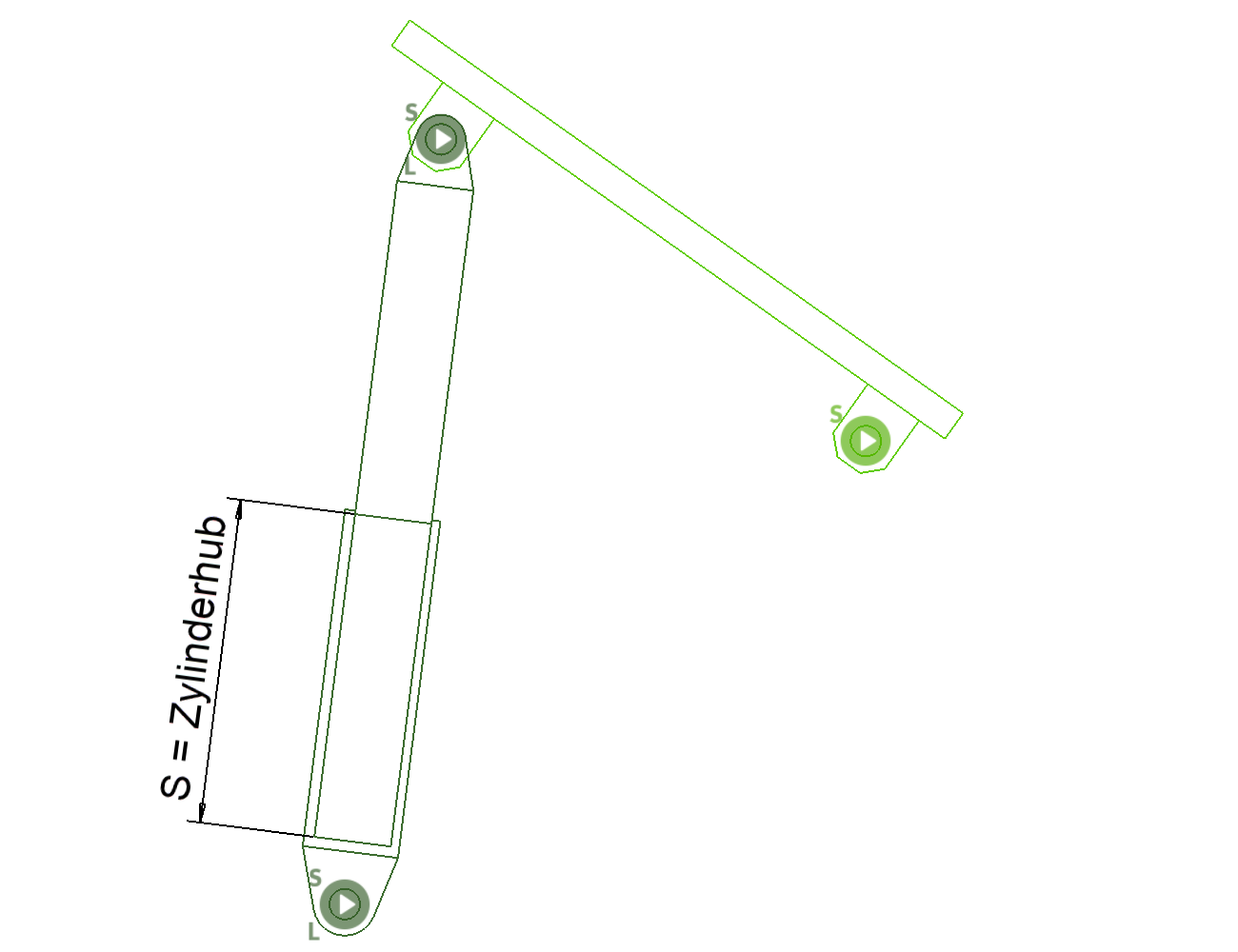
Cylinder stroke S = step size x repetition
The step size defines the speed with which the system moves and the number of repetitions results in the desired stroke in the current unit.
With this kinematic system, the individual parts do not have to have any points in common, since the movements are calculated through the 3 points and the distance of "S" (see sketch).
Further levers with rotation points can be attached to the start lever.
Sample: