Lever systems
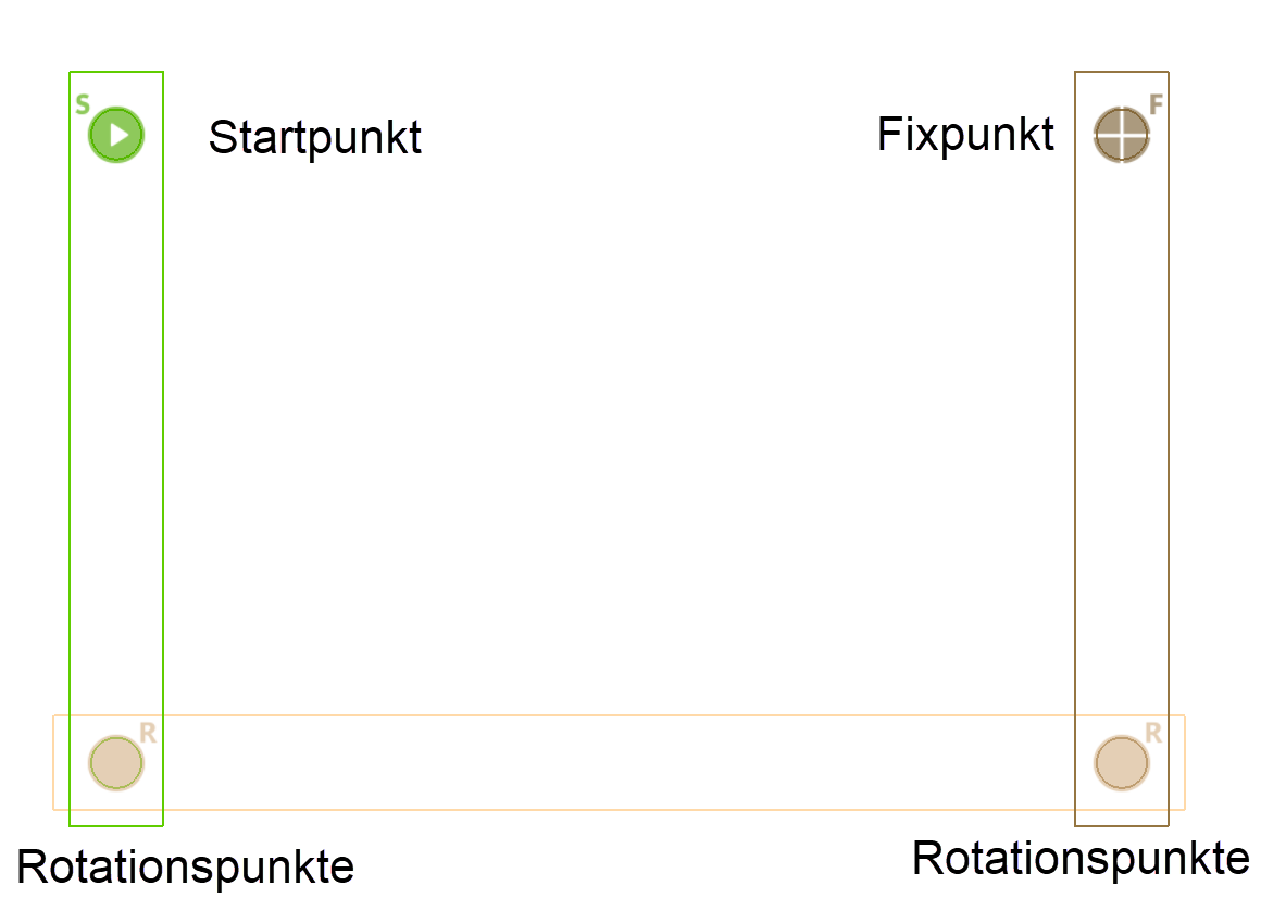
Start point
![]()
This point defines the starting point of the lever system. This means that during a rotation, for example, this lever is turned through the specified angle, and all other lever movements depend on the rotation of the start lever. Only one start point can be defined for each lever system (the symbol is greyed out after the first designation and can no longer be selected).
A start point is necessary for every kinematic system with the exception of the cam. The start point is marked with a symbol that includes an "S" in the preset colour.
Rotation point
![]()
These points define the rotation point of a lever, the position of which changes due to the movement of the kinematics system. Movable levers are connected to one another with the point of rotation. That means there are always at least 2 levers meeting at a rotation point, whereby the circles must have the same centre point (radius is irrelevant).
The ROTATION POINT function is self-retaining, which means that several definitions can be carried out one after the other (use Esc to end this function). In this way, all the rotation points of the lever system can be identified at once.
Each point of rotation is marked with a symbol that includes an "R" in the preset colour.
Fixed point
![]()
This point defines the rotation point of a lever, the position of which is always fixed (immovable point around which the lever rotates). Each lever may only have one fixed point.
Each fixed point is marked with a symbol that includes an "F" in the preset colour.
Kinematic systems are defined with start, fixed and rotation points, in which only rotations take place (no guide contour).
Sample:
Depiction with colour assignments
(Colour mode pen)


Definition line
Improved · 16 R1 · Improvements
![]()
Only one line of a lever in the system can be marked as a definition line. When the kinematics are executed, the system stops when the set definition angle is reached. The definition angle is set in the parameter window.
This enables a lever system to be rotated to the desired definition angle.
Setting the Definition line
To set the definition line, a line must already be drawn in the graphics window.
Once the icon (insert icon here) is selected the line can be chosen. The automatic orientation of the line is the same as the direction it was originally drawn in.
The orientation can be quickly identified by the shapes that mark the definition line. The circle shape is on the starting side and the diamond on ending side. To switch the direction, the ends of the line must be switched by manipulating the handles on each end of the line, but it is simpler to adjust the angle according to the direction of the line.
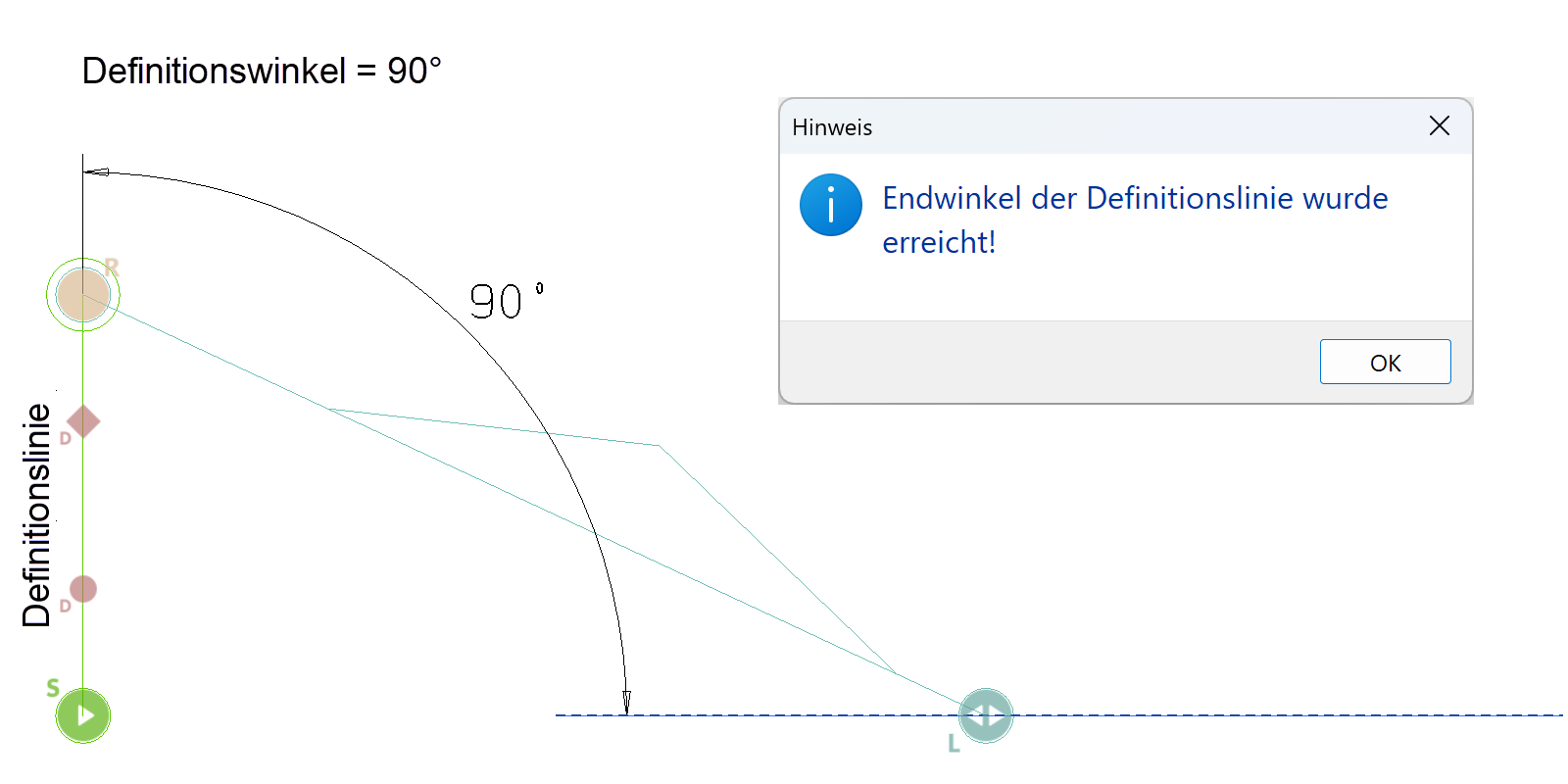
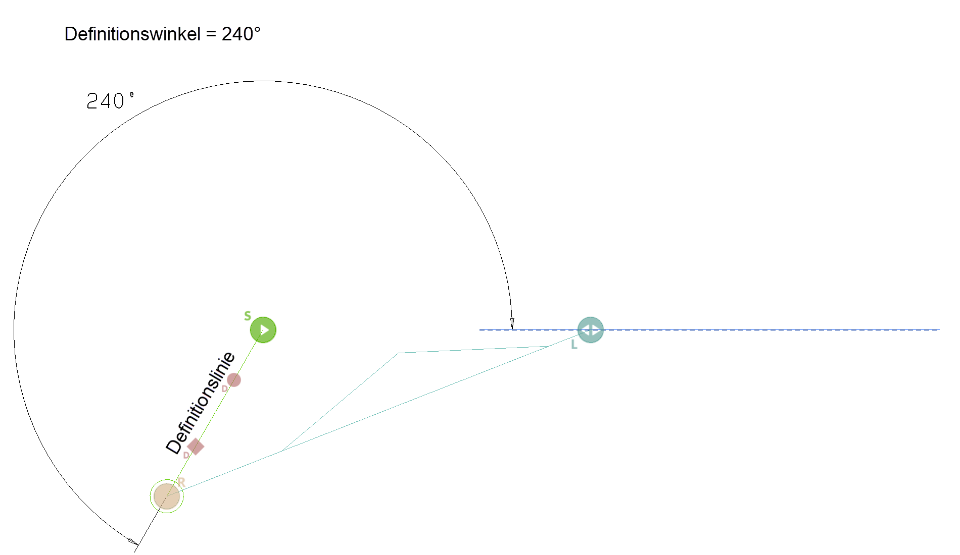
Setting the angle of the definition line
The angle of the definition line to be reached should be specified in degrees in the range from 0 - 360 and is set in the “Advanced setting” section of the parameters menu for the kinematic system.
Note
The angle of rotation must always be less than 90 degrees where the definition line is concerned!
The system has reached the specified definition angle when the message "Final angle of definition line has been reached" is displayed. With this sequence of movements, the setting ENDLESS LOOP is recommended for the repetitions, since the number of repetitions must be sufficient for an interpolation of the definition angle.
This means that the system is rotated with the specified angle of rotation until the final angle is exceeded. Then it is turned back with half the angle until the final angle is undershot again. Then it is rotated in the opposite direction again with the halved angle .... If the number of repetitions is too small, the message "Rotation ended" appears and the final angle was not reached.
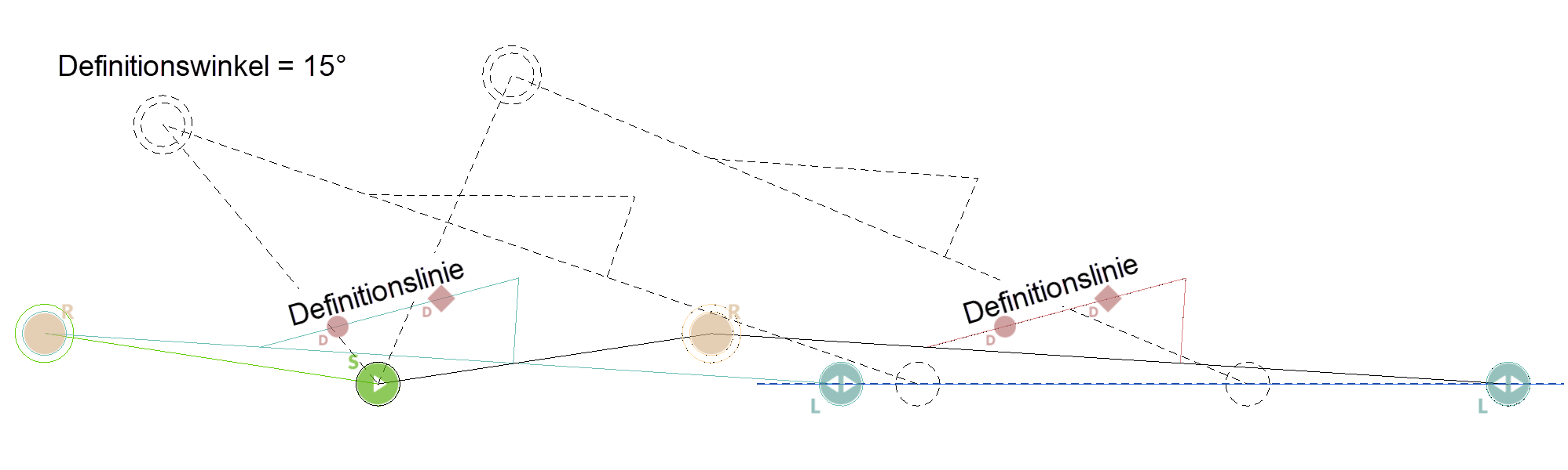
Examples of various definition angles on different elements
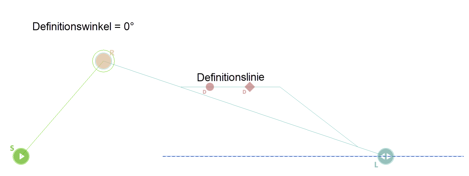
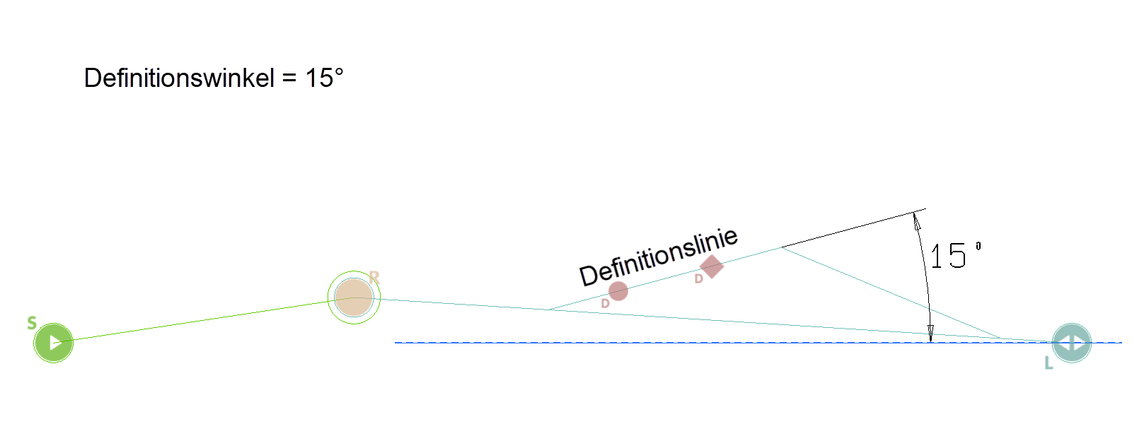
There is also the possibility that a definition line reaches a specified value (e.g. 15 °) twice. In this case, the kinematics system can be moved back and forth between the two end positions.