Capture Functions
Auto-capture mode
The cursor responds as soon as it is positioned near a capture point and indicates the type of capture point by means of a symbol.


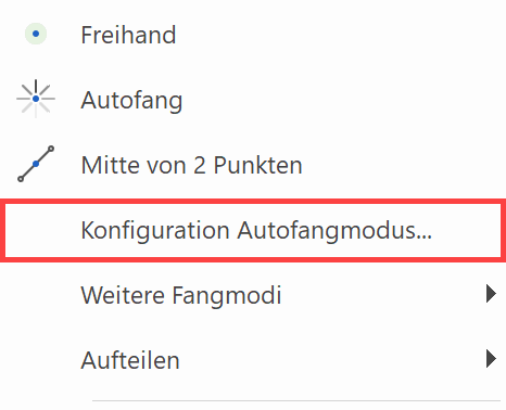
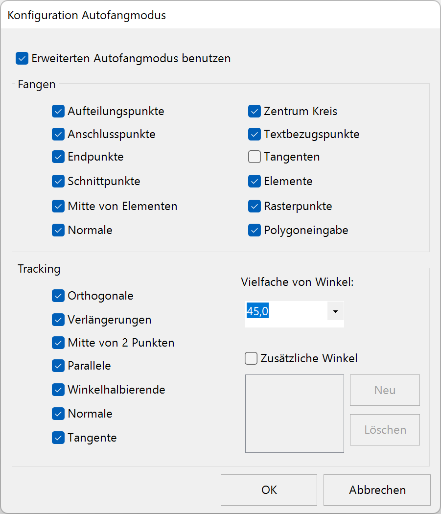
In the AUTO-capture mode configuration, the individual capture options are enabled or disabled in the context menu.
Crosshair
Display
The most frequently used capture functions can be distinguished by the different crosshair.
| Icon | Crosshair type | Graphics window depiction |
|---|---|---|
| Free |  |
|
| Point |  |
|
| Section point |  |
|
| Auxiliary-geometry section point | |
|
| To element |  |
|
| Centre circle |  |
|
| Normal on circle/line |  |
|
| Middle of element |  |
|
| Middle of 2 points |  |
Orthogonal with arrow key
When the arrow key is pressed on the keyboard, the crosshair only moves orthogonally on the screen. The Up Down arrow keys lock the crosshair vertically and the Left Right arrow keys lock the crosshair horizontally.
Tip
As soon as you lock the crosshair horizontally or vertically with the arrow keys, you can also specify a reference point with any capture mode using the cursor.

For the end point of the line, first select point capture, then press and hold the left or right arrow key and move the cursor to the corner of the rectangle. You will notice that the crosshair snaps to the corner as you approach it.
Alternative capture modes
AUTO-capture and free capture modes are usually sufficient. The capture modes that appear on the first page of the context menu can be set in the Further Capture modes menu item.
Auto-capture
|
|
Capture mode toolbar |
| Context menu (right mouse button) |
This capture mode is a convenient capture function that searches hierarchically for various capture criteria.
When this function is activated, the subsequently digitised position is evaluated according to the criteria listed below and the crosshair is positioned accordingly.
Search sequence:
- No point found, then section point
- No point found, then auxiliary-geometry section point
- No point found, then element
- No element found, then freehand
Tip
You can recognise which capture function is being used currently to focus on a position by the depiction of the crosshair.
This capture function always finds a position on the screen.
Orthogonal locking
When the cursor is at a right angle to the reference point, a temporary auxiliary-line is displayed and the cursor easily snaps to this position.
To Auto-capture
|
|
Capture mode toolbar |
| Context menu (right mouse button) |
Using the TO option, it is possible to select any reference point regardless of the current location (small white rectangle) and to effect a movement from here (e.g. by entering values).
When this function is activated, the subsequently digitised position (reference point) is evaluated according to the criteria listed below.
Search sequence:
- No point found, then section point
- No point found, then auxiliary-geometry section point
- No point found, then element
- No element found, then freehand
Now the final position of the crosshair must be determined (e.g. by entering values).
Tip
The MOVE AUTOMATICALLY TO capture mode can also be supplemented with an additional capture mode:
If the destination point is a certain distance from the centre of a circle, it can be reached with the following input: Select the MOVE AUTOMATICALLY TO capture mode and select CENTRE CIRCLE capture. Place the reference point into the centre of the circle and now enter the desired distance from this point.
Freehand
|
|
Capture mode toolbar |
| Context menu (right mouse button) |
This function allows you to position the crosshair at any freely selectable location.
Point capture
|
|
Capture mode toolbar |
| Context menu (right mouse button) |
This function allows you to position the crosshair at the start or end of an existing drawing element.
When this function is activated, the crosshair is tilted through 45°. When you approach a point, the crosshair becomes orthogonal and you can confirm the point by clicking with the left mouse button. Then the crosshair jumps to this point.

Section point
|
|
Capture mode toolbar |
| Context menu (right mouse button) |
This capture mode allows you to position the crosshair at the intersection of two drawing elements, of one drawing element and an auxiliary-geometry element, or of two auxiliary-geometry elements.
When this function is activated, the crosshair is tilted through 45°. When you approach a section point, the crosshair becomes orthogonal and you can confirm by clicking with the left mouse button. Then the crosshair jumps to this section point.

Auxiliary-geometry section point
|
|
Capture mode toolbar |
| Context menu (right mouse button) |
This function allows you to position the crosshair at the intersection of two auxiliary-geometry elements.
When this function is activated, the crosshair is tilted through 45°. When you approach an auxiliary-geometry section point, the crosshair becomes orthogonal and you can confirm by clicking with the left mouse button. Then the crosshair jumps to this auxiliary-geometry section point.

Centre circle
|
|
Capture mode toolbar |
| Context menu (right mouse button) |
This function allows you to go to the centre of a circle or arc.
When this function is activated, the crosshair is tilted through 45°. When you approach a circle or arc (drawing element or auxiliary-geometry), the crosshair becomes orthogonal and jumps to the centre. Confirm with the left mouse button.

Tip
The centre of the circle may also lie outside the drawing format.
Middle of element
|
|
Capture mode toolbar |
| Context menu (right mouse button) |
This function allows you to go to the centre of a drawing element.
When this function is activated, the crosshair is tilted through 45°. When you approach a drawing element, the crosshair becomes orthogonal and jumps to its centre. Confirm with the left mouse button.

Tip
This function can only be used for drawing elements.
Middle of 2 points
|
|
Capture mode toolbar |
| Context menu (right mouse button) |
This function allows you to go to the middle of 2 points.
When this function is activated, the two points must be clicked. Then the crosshair jumps to the middle of the imaginary line connecting the specified points.

Normal to element
|
|
Capture mode toolbar |
| Context menu (right mouse button) |
This function allows you to automatically calculate and display the normals to a drawing element or auxiliary-geometry (straight and circle/arc) from the current position.
When this function is activated, the crosshair is tilted through 45°. When you approach a drawing element or auxiliary-geometry, the crosshair becomes orthogonal and jumps to the section point that is normal to the current position. Confirm with the left mouse button.
Tip
The section point of the normals from the current position to the selected element need not necessarily be on this selected element, but may lie outside it.

Distance to element from point
|
|
Capture mode toolbar |
| Context menu (right mouse button) |
This capture mode allows you to position the crosshair on an element and to specify a distance to the nearest point.
When this function is activated, the element in question must be clicked. Then the crosshair jumps to the point nearest to the element. Now the desired distance from this point can be specified. Then the crosshair is set to the calculated position.
Workshop
Distance to element from point
Place a window in ELITECAD Architecture in a wall one metre from the wall corner.
Select the window.
Image 1: Activate the Distance to element from point capture mode and click on the wall in which the window is to be placed, near to the corner from which you wish to specify the distance. Do not click in the corner. Otherwise, you will not know whether the window will be placed in the horizontal wall or the vertical one.
Image 2: When you click on the wall, the  marker jumps to the corner. Check whether it is the correct corner. If you have clicked on the inside of the wall, it must not switch to the outside. If the marker is in the wrong location, select capture mode again and click the wall nearer to the corner.
Image 3: In the input line, enter and confirm the distance. The marker jumps to the specified position and the window can be placed. Because you click on the element to which the distance is to be applied, there is no need to enter a direction using x and y values or +/-.

Tangent
|
|
Capture mode toolbar |
This function allows you to calculate automatically the tangents from an initial location (defined location outside the circle) to a selected circle or arc.
When this function is activated, the crosshair is tilted through 45°. When you approach a circle or arc (drawing element or auxiliary-geometry), the crosshair becomes orthogonal and jumps to the tangent point. Confirm with the left mouse button.
Tip
This process can also be used for measuring.
To element
|
|
Capture mode toolbar |
| Context menu (right mouse button) |
This capture mode allows you to specify an existing drawing element or auxiliary-geometry (line or arc) as a guide for the crosshair.
When this function is activated, the crosshair is tilted through 45°. When you approach a drawing element or auxiliary-geometry, the crosshair becomes orthogonal and you are guided along the element as if on "tracks". Confirm with the left mouse button when you have reached the required position.

Grid
|
|
Capture mode toolbar |
This function allows you to position the crosshair in a defined grid. This is particularly useful for electrical and hydraulic plans, and for the exact positioning of the scale and text.
When this function is activated, the crosshair jumps to the nearest grid point.
Keep orthogonal
|
|
Capture mode toolbar |
| Context menu (right mouse button) |
This function allows you to move the crosshair freehand while keeping it horizontal or vertical. It is particularly suitable for underlining, information arrows, centre lines, etc. and also for positioning objects.
When this function is activated, the crosshair is restricted to horizontal and vertical movements when it is moved freehand. Whether it moves horizontally or vertically depends on what is nearest to the current crosshair position.
Tip
The arrow keys Up Down Left Right on the keyboard have the same effect as this capture mode.
Keep horizontal
|
|
Capture mode toolbar |
| Context menu (right mouse button) |
This function forces the crosshair to be guided in a horizontal direction. This function can be combined with the other capture functions. Missing parameters can thus be constructively determined directly from the drawing without the corresponding measurements having to be taken.
When the function is activated, the crosshair is guided horizontally on the screen. A second capture function can now be selected and used in combination.
Tip
Pressing and holding the arrow keys Left Right on the keyboard have the same effect as this capture mode.
Keep vertical
|
|
Capture mode toolbar |
| Context menu (right mouse button) |
This function forces the crosshair to be guided in a vertical direction. This function can be combined with the other capture functions. Missing parameters can thus be constructively determined directly from the drawing without the corresponding measurements having to be taken.
When the function is activated, the crosshair is guided vertically on the screen. A second capture function can now be selected and used in combination.
Tip
Pressing and holding the arrow keys Up Down on the keyboard have the same effect as this capture mode.
Element
|
|
Capture mode toolbar |
| Context menu (right mouse button) |
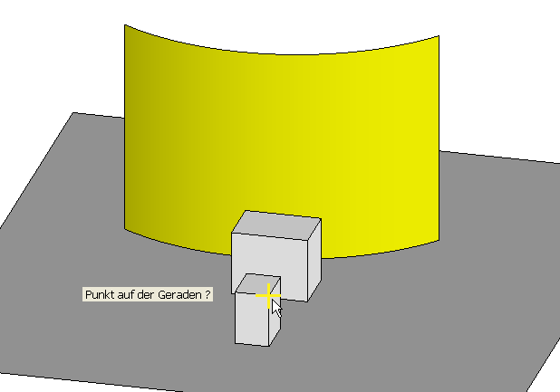
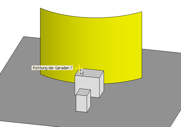
This capture mode allows you to position the crosshair on an imaginary “beam” in the direction of a definable drawing element.
When this function is activated, you click on the element that determines the direction. The crosshair is now locked on this “beam”.
Centre edge
|
|
Capture mode toolbar |
| Context menu (right mouse button) |
This function allows you to go to the middle of an edge in 3D.
When this function is activated, the crosshair is tilted through 45°. When you approach a 3D edge, the crosshair becomes orthogonal and jumps to the centre of the edge. Confirm with the left mouse button.
Centre surface
|
|
Capture mode toolbar |
| Context menu (right mouse button) |
This function allows you to go to the middle of a surface in 3D.
When this function is activated, the crosshair is tilted through 45°. When you approach a 3D surface, the crosshair becomes orthogonal and jumps to the centre of the surface. Confirm with the left mouse button.
Tip
The centre of a surface is calculated as the centre of gravity.
This capture mode cannot be used for the lateral surfaces of boxes and extruded shapes or for trimmed surfaces.
Section of work plane with surface
|
|
Capture mode toolbar |
This function allows you to capture a section point between a surface edge and the current work plane.
When this function is activated, the crosshair jumps, but a surface edge must be designated with the cursor. When you approach an edge, the crosshair jumps to the section with the current work plane.

Line/surface section
|
|
Capture mode toolbar |
This function allows you to capture a section point between a straight and a surface.
When you select this function, you are prompted for a point on the straight (start point) and its direction (end point). Then the surface that it will intersect must be entered. The marker is set to the section point as a result.
Workshop
Line/surface section capture mode
The line is specified by two points. Points that do not lie on the current work plane can also be selected with the POINT capture mode.
Once the two points of the line have been entered, the surface must be defined.

A virtual line is generated along the two specified points. The marker is set at the point where the line intersects the surface of the extrude.
Quadrants
|
|
Capture mode toolbar |
The snap mode "quadrants" is only available in ELITECAD Mechanics.
It snaps four special points on a circle or arc – especially intended as an assistance for diameter measurements.
Set the workspace in the plane of the circle before applying this snap function. The points represent the quadrant boundaries on the arc or circle relative to the X-Y plane of the current workspace. It is not mandatory to set the workspace in the circle plane.
In detail, the snap mode snaps the intersection points of the arc or circle with a plane that is normal to the X- or Y-direction of the current workspace and goes through the centre of the circle. If the Z-direction of the current workspace is orthogonal to the normal direction of the circle, the Z normal plane is used for snapping instead of the X normal plane, so to say the Y-Z plane.
The procedure of the snap function is as follows:
- Establishment of an area selected with the mouse pointer.
- Establishment of the intersection point of the selection beam with this surface.
-
Establishment of the closest edge near the selected point.
If the edge is circular:
-
Establishment of the four quadrant boundaries relative to the work plane, if possible.
- Establishment of the quadrant edge closest to the intersection point.
Tip
In order to facilitate correct snapping the mouse cursor should be positioned on the surface to which the edge belongs, as close as possible to that edge. The snap mode may eventually not work properly for surfaces generated in old ELITECAD versions or surfaces imported from other interfaces.
Move crosshair
|
|
Capture mode toolbar |
The function performs a SINGLE movement step, independent of the current position of the crosshair.
After activating the function, the crosshair can be moved. The point input can be done by value input. The procedure can be repeated for multiple consecutive relative movements.
To point
|
|
Capture mode toolbar |
This function allows selecting a point as a new reference point for point inputs, independent of the current position (indicated by the marker – a small white rectangle). The new reference point is then used to enter a movement relative to it (e.g. by entering a value). The result is the distance between the current position (start position) and the end position of the crosshair.
After activating the function and moving the crosshair near a point, it jumps to it. From here, the new position of the crosshair is defined relatively (e.g. by value input).
Tip
The current position is not modified by the snap mode TO POINT. Only by further inputs (e.g. by entering a value), the position is changed.
To section
|
|
Capture mode toolbar |
This function allows selecting an intersection point as a new reference point for point inputs, independent of the current position (indicated by the marker – a small white rectangle). The new reference point is then used to enter a movement relative to it (e.g. by entering a value). The result is the distance between the current position (start position) and the final position of the crosshair.
After activating the function and moving the crosshair near an intersection point, it jumps to it. From here, the new position of the crosshair is defined relatively (e.g. by value input).
Tip
The current position is not modified by the snap mode TO SECTION. Only by further inputs (e.g. by entering a value), the position is changed.
To centre circle
|
|
Capture mode toolbar |
This function allows selecting the centre of a circle as a new reference point for point inputs, independent of the current position (indicated by the marker – a small white rectangle). The new reference point is then used to enter a movement relative to it (e.g. by entering a value). The result is the distance between the current position (start position) and the final position of the crosshair.
After activating the function and moving the crosshair near a circle, it jumps to its centre. From here, the new position of the crosshair is defined relatively (e.g. by value input).
Tip
The current position is not modified by the snap mode TO CENTRE CIRCLE. Only by further inputs (e.g. by entering a value), the position is changed.
To middle of element
|
|
Capture mode toolbar |
This function allows selecting the middle point of an element as a new reference point for point inputs, independent of the current position (indicated by the marker – a small white rectangle). The new reference point is then used to enter a movement relative to it (e.g. by entering a value). The result is the distance between the current position (start position) and the final position of the crosshair.
After activating the function and moving the crosshair near an element, it jumps to its middle point. From here, the new position of the crosshair is defined relatively (e.g. by value input).
Tip
The current position is not modified by the snap mode TO MIDDLE OF ELEMENT. Only by further inputs (e.g. by entering a value), the position is changed.