Selecting
General
For each selection, the following principles are true:
- A selection is highlighted in magenta.
- If possible, the corresponding property bar and handles of the selection are displayed.
- A selection can be further manipulated with the manipulation functions.
Selection by mouse click
A click with the left mouse button in the graphics window means SELECTING and EDITING. If there is nothing selected and no special selection function is active, the selection by rectangle starts.
With a single click, the property bar of the selected object is displayed. A double click opens, if available, the main parameter dialog window. The text has different behaviour – a double click on texts starts the editing function of the text.
The Shift key enables adding or removing something to the selection. Selected objects are displayed in magenta and their corresponding handles are shown, provided there is no mixture of incompatible objects.
Selection by rectangle
The selection rectangle is used to make a selection. The rectangle is either defined by two clicks or by a click and dragging with the mouse. If the selection is made from left to right, a blue rectangle appears, which selects only those parts that are fully included in it. If the selection is made from right to left, a green rectangle appears, which selects all parts that it covers. You can use Shift + Leeft click to select additional parts or to deselect parts.
 |
 |
 |
 |
Selection by parameter
|
|
Select toolbar |
| Edit menu > Select > Parameter |
With this selection function, a selection is made using an objects parameters. Therefore, an object has to be selected in the graphics window. If an object is already selected when the function is launched, the query is obsolete and the selected object is used immediately.
All parameters of the selected object are displayed in a dialog window in a list. These parameters are available as search criteria.
Example for hatching parameters:
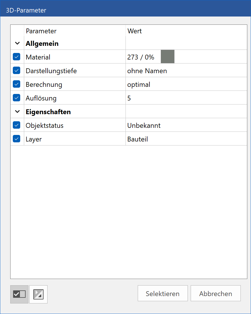
Selection
In this column, you can select, which parameters should be used for the search and which should not. If the box is ticked, the parameter will be used.
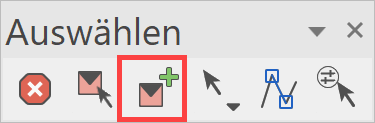
All / None
![]()
These options allow you to select or deselect all parameters.
Open / close all groups
![]()
With these functions, all parameter groups can be opened and closed simultaneously.
Select

With a click on this button, the selection will be made.
Selection settings
Selection with group/class/level
Working with the classification structure model/group/class/level is possible, if the switch "Selection with group/class/level" is enabled under SETTINGS > OPTIONS > WORKING PARAMETERS > EDIT.
The default setting for ELITECAD Mechanics is working with the classification structure and in ELITECAD Architecture without classification structure.
Tip
It is recommended not to change the presets.
Selection with element part
|
|
Selecting toolbar |
The part selection mode allows access to:
- Single lines of a polygon
- Single dimension of a chain dimension
- 3D-Object without 2D
- The last 3D operation (e.g. Boolean operation)
The selection mode is permanently changed in selection toolbar.
For a single application of a part selection, a selection per Alt + Left click is available.
There is no access in part selection mode for objects generated by the program.
Selecting toolbar
The preset in ELITECAD is a selection per mouse click or per selection rectangle. Special functions for selecting are launched directly via the menu EDIT > SELECT. Functions related to selecting which are used very often are combined into the SELECTING toolbar.
The available functions in the toolbar depend on the setting SELECTION WITH GROUP/CLASS/LEVEL. This is the reason why the presets differ between ELITECAD Architecture and Mechanics. The functions ABORT and SELECTION ELEMENT/PART are always visible.
Selection mode mouse click/rectangle and layer
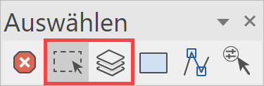
One can switch between the two selection modes mouse click/rectangle and layer. Selection in layer mode selects parts based on the layer they belong to.
Selection image
Selection of all constructed parts.
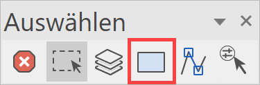
Selection mode mouse click/rectangle
One can switch between the two modes mouse click/rectangle. In the object mode, objects are always selected completely.
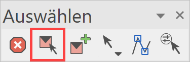
New object
This function starts a new component (same as with NEW CLASSIFICATION, see chapter Managing > Classification).
Tip
An existing component is ACTIVATED by Ctrl + Left click . Activating an object also activates the workplane of the selected object. The classification of the selected object becomes the active classification.
Select
Offers quick access to the select functions.
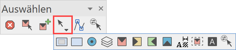
Object selection mode
![]() In the object mode, objects are always selected completely.
In the object mode, objects are always selected completely.
Select
All
|
|
Select toolbar |
| Edit menu > Select > All |
This function selects everything, including quantities not shown on the screen.
Image
|
|
Select toolbar |
| Edit menu > Select > Image |
With this function, the current image is selected, i.e. just what is shown on the screen currently, but regardless of the zoom.
Layer
|
|
Select toolbar |
| Edit menu > Select > Layer |
This function includes objects depending on their layers in the selection.
When you activate the function, the layer is selected. There are several options for this:
- If the selection is made by clicking, several layers can be marked with the crosshair. To remove a layer from the selection again, simply click it again. Once you have specified all the layers, complete the function with Enter .
- The selection can be made by entering the layer name in the input line. When you confirm the name with Enter , more layers can be clicked or the selection ended with Enter . Several layer names can be entered together in the input line. Each layer name must be separated with a comma.
- If you only press Enter , the current layer is selected.
Block
|
|
Select toolbar |
| Edit menu > Select > Block |
With this function, the lines contained by a polygon are selected if the elements are completely contained within the polygon.
Note
Architectural objects such as walls, ceilings, windows, etc., or mechanical objects such as screws, profiles, etc. cannot be selected with this function. The objects are protected.
After the function is activated, the elements in question are enclosed within a polygon. The polygon chain is closed by clicking again on the last position.
Section
|
|
Select toolbar |
| Edit menu > Select > Section |
Lines contained by a polygon are selected and the lines are severed at the point where they intersect the polygon.
Note
Architectural objects such as walls, ceilings, windows, etc., or mechanical objects such as screws, profiles, etc. cannot be selected with this function. The objects are protected.
After the function is activated, the elements in question are enclosed within a polygon. The polygon chain is closed by clicking again on the last position.
Exterior block
|
|
Select toolbar |
| Edit menu > Select > Exterior block |
With this function, the lines excluded by a polygon are selected if the elements are completely outside the polygon.
Note
Architectural objects such as walls, ceilings, windows, etc., or mechanical objects such as screws, profiles, etc. cannot be selected with this function. The objects are protected.
After the function is activated, the elements in question are excluded outside a polygon. The polygon chain is closed by clicking again on the last position.
Exterior section
|
|
Select toolbar |
| Edit menu > Select > Exterior section |
Lines excluded by a polygon are selected and the lines are severed at the point where they intersect the polygon.
Note
Architectural objects such as walls, ceilings, windows, etc., or mechanical objects such as screws, profiles, etc. cannot be selected with this function. The objects are protected.
After the function is activated, the elements in question are excluded outside a polygon. The polygon chain is closed by clicking again on the last position.
Object
|
|
Select toolbar |
| Edit menu > Select > Object |
The object mode is only available in ELITECAD Mechanics and adds objects to the selection. It is intended primarily for self-defined components, because the objects generated by the program are always chosen as a whole. With the corresponding shortcut key F4 (default), the object mode can be activated and deactivated.
In object mode, no rectangle selection is possible. Instead, the function EDIT > SELECT > BLOCK MODEL can be used.
After activating the function, the objects are selected. There are several possibilities:
- If the selection is made by clicking, several objects can be marked with the crosshair. To remove an object from the selection, it has to be clicked again. If you have specified all objects, the function must be terminated with Enter .
- If you only press Enter , the current object will be selected.
Model
|
|
Select toolbar |
| Edit menu > Select > Model |
Edit menu > Select > Model
This function includes objects into the selection based on their model name.
After activating the function, the models are selected. There are several possibilities:
- • If the selection is made by clicking, several models can be marked with the crosshair. To remove a model from the selection, it has to be clicked again. If you have specified all models, the function must be terminated with Enter .
- • If the selection is made by specifying the model name, all models with this name are selected. After confirming Enter the name, further models can be clicked or the selection can be ended with Enter . It is also possible to enter several model names in the input line. The respective model names must be separated by a comma.
- If you only press Enter , the current model will be selected.
Block model
|
|
Select toolbar |
| Edit menu > Select > Block model |
With this function, the lines excluded by a polygon, with only one element of the model partially contained in the polygon. The models defined by the polygon are selected entirely.
After activating the function, the patterns affected by the polygon are marked. The polygonal chain is completed by a second click on the last position. Subsequently, the selection made can be manipulated.
Tip
In contrast to the selection functions SECTION and BLOCK, the BLOCK MODEL selection function also includes all 3D and object information. An architectural or mechanical object can therefore be processed further.
Group
|
|
Select toolbar |
| Edit menu > Select > Group |
This function includes objects into the selection based on their group name.
Tip
The selection GROUP only appears in the selection options of the manipulations if the option SELECTION WITH GROUP / CLASS / LEVEL is activated in the working parameters.
After activating the function, the groups are selected. There are several possibilities:
- • If the selection is made by clicking, several groups can be marked with the crosshair. To remove a group from the selection, it has to be clicked again. If you have specified all groups, the function must be terminated with Enter .
- • If the selection is made by specifying the group name, all groups with this name are selected. After confirming Enter the name, further groups can be clicked or the selection can be ended with Enter . It is also possible to enter several group names in the input line. The respective group names must be separated by a comma.
- If you only press Enter , the current group will be selected.
Class
|
|
Select toolbar |
| Edit menu > Select > Class |
This function includes objects into the selection based on their class name.
Tip
The selection CLASS only appears in the selection options of the manipulations if the option SELECTION WITH GROUP / CLASS / LEVEL is activated in the working parameters.
After activating the function, the classes are selected. There are several possibilities:
- • If the selection is made by clicking, several classes can be marked with the crosshair. To remove a class from the selection, it has to be clicked again. If you have specified all classes, the function must be terminated with Enter .
- D• If the selection is made by specifying the class name, all classes with this name are selected. After confirming Enter the name, further classes can be clicked or the selection can be ended with Enter . It is also possible to enter several class names in the input line. The respective class names must be separated by a comma.
- If you only press Enter , the current class will be selected.
Level
|
|
Select toolbar |
| Edit menu > Select > Level |
This function includes objects into the selection based on their level name.
Tip
The selection LEVEL only appears in the selection options of the manipulations if the option SELECTION WITH GROUP / CLASS / LEVEL is activated in the working parameters.
After activating the function, the levels are selected. There are several possibilities:
- • If the selection is made by clicking, several levels can be marked with the crosshair. To remove a level from the selection, it has to be clicked again. If you have specified all levels, the function must be terminated with Enter .
- • If the selection is made by specifying the level name, all levels with this name are selected. After confirming Enter the name, further levels can be clicked or the selection can be ended with Enter . It is also possible to enter several level names in the input line. The respective level names must be separated by a comma.
- If you only press Enter , the current level will be selected.
Attribute
|
|
Select toolbar |
| Edit menu > Select > Attribute |
This function includes objects into the selection based on their attributes.
Tip
With the help of the INFORMATION > MODEL INFORMATION function, the various attributes and their values can be viewed.
After activating the function, the desired attribute name is entered in the input line. Thereafter, the value of the attribute, which is to be selected, is entered. This process is carried out as often as required until the appropriate selection has been made and it is ended with Enter .
Tip
The prerequisite is that a corresponding attribute file is loaded with the function ATTRIBUTE PARAMETERS.
Buffer
The buffer provides a special selection function. The buffer can temporarily store a mixed selection.
The buffer will remain until the drawing is deleted.
Tip
A buffer is not stored in a work copy.
Select buffer
|
|
Buffer toolbar |
| Edit menu > Select > Buffer |
This function is used to select a defined buffer for subsequent manipulation(s).
After activating the function, the desired buffer name is entered in the input line. The buffer content is marked and can then be further processed with the manipulation functions.
In buffer
|
|
Buffer toolbar |
| Menu Edit > Select > In Buffer |
This function assigns the defined selection to the specified buffer, whereby it adds to a previously existing content.
The selection must be defined before activating the function. Then the function is opened and the name of the desired buffer is entered. The previously-made selection is added to the buffer contents.
From buffer
|
|
Buffer toolbar |
| Menu Edit > Select > From Buffer |
This function removes the selection made from the specified buffer.
The selection must be defined before activating the function. Then the function is opened and the name of the desired buffer is entered. The previously-made selection is removed from the buffer.
Block copy in buffer
|
|
Buffer toolbar |
This function copies the lines delimited by a polygon to the specified buffer. Only lines that are completely contained in the polygon are affected by this operation. This function creates copies, the original objects remain unchanged.
After activating the function, the polygonal chain limits the affected elements. The polygon is completed by a second click on the last position. After closing the polygon, the name of the buffer must be entered in the input line. Now the elements are copied and can be called up and manipulated by means of the function SELECT BUFFER.
Section copy in buffer
|
|
Buffer toolbar |
This function copies the lines delimited by a polygon to the specified buffer, dividing the lines at the intersection with the polygon. This function creates copies, the original objects remain unchanged.
After activating the function, the polygon chain limits the affected elements. The polygon is completed by a second click on the last position. After closing the polygon, the name of the buffer must be entered in the input line. Now the elements are copied and can be called up and manipulated by means of the function SELECT BUFFER.
Clear buffer
|
|
Buffer toolbar |
| Menu Edit > Select > Clear Buffer |
This function clears the specified buffer. That means, after calling the function and specifying the buffer name, the affected buffer is empty.