Attributes
As mentioned at the beginning of this chapter, all required non-graphic information are assigned to the components in ELITECAD with corresponding attributes and managed directly within the drawing. Attributes are defined in attribute files and can be adapted to your company standard from these files.
The current standard attribute file for mechanics can be found in the directory <ELITECAD-installation path>\u\<version>\me\glob\dflt\en\me.attr
Note
Changes to the standard files in the ELITECAD installation directory are valid for all CAD workstations in the network. We therefore recommend that you only make these changes together with the responsible system administrator in your company.
Adapted and optimised files in the installation directory of ELITECAD will be overwritten again during the next setup. You should therefore also save your changes in your file directories so that you can reactivate your adjustments in the event of updates.
Define attributes
All attributes accessible by the user can be freely defined with their designation and design. Use the generation program for this /usr/<version>/util_x64/ReadAttr.exe in the installation directory of ELITECAD.
Before you plan to change the formatting of attributes, you should backup the current attribute file. When the ReadAttr.exe program is opened, the file selection dialog for entering the attribute file appears. Change the setting to the directory <ELITECAD-installation path>\u\<version>\me\glob\dflt\en and double-click the file me.attr.
The input dialog appears

In the "NAME" field, select the attribute name that is to be reformatted.
With the information in the fields
- Type
- Orientation
- Length
- Decimals
- Description
determine the representation of this component information in the bill of material form.
In addition to the selection of existing attributes, new attributes can also be added. To do this, write the attribute name in the "NAME" field, format the display of this attribute and then confirm with NEW. Similarly, you can also DELETE attributes from the attribute file.
This formatting of the attributes has its full effect on bill of material that are written to ASCII files or to the CAD information window. (see setting parameters for Bill of material output).
For the bill of material output as a CAD sample on the drawing or on EXCEL files, only the parameters from the "Type" input field apply. These formatting settings are controlled by the attribute file. The text alignment is determined by the current text parameters in the selected bill of material template.
Edit conversion lines:
For the evaluation of drawings that have been created on other CAD systems (CAD 400), the attributes can be converted into ELITECAD attributes.
When you select the function, the input dialog appears:
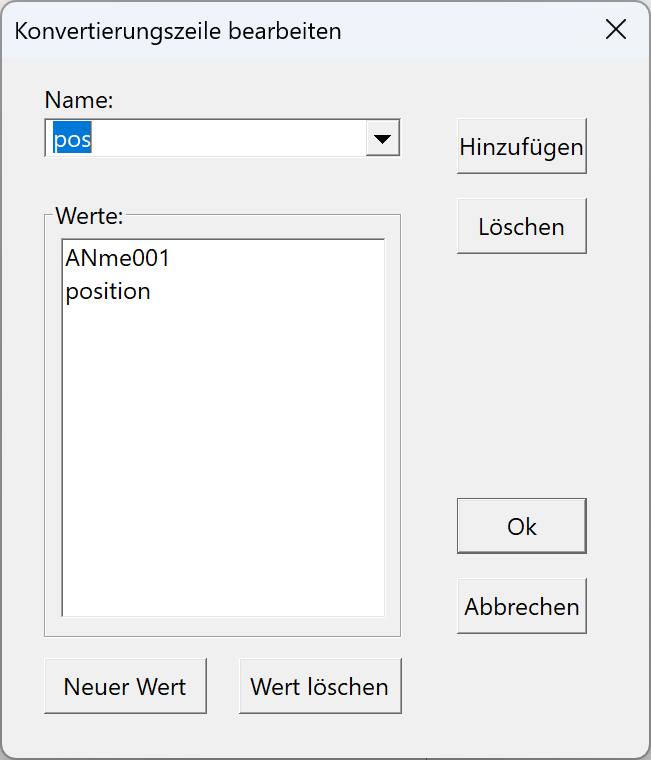
Enter the ELITECAD attribute in the NAME field and write the name of the conversion rule and the name of the external attribute in the VALUES field.
The NEW VALUE and DELETE VALUE buttons to add or remove values.
With INSERT the entry is added to the attribute file.
With DELETE this entry is removed.