Chain Dimension
|
|
Toolbar * Create new |
| Lay-out menu > Dimensions > Chain dimension |
This function is used to enter a sequential dimension.
Chain dimension property bar
You can select the dimension's main values in the property bar. On the right end, you can select options for defining dimension points. However, the dimensions are fine-tuned with the dimension parameters.
The property bar is different for ELITECAD Architecture and Mechanics.


Dimension parameters
![]()
Opens the Dimension parameters dialog window.
Dimension positioning
![]() - Automatic
- Automatic
![]() - Horizontal
- Horizontal
![]() - Vertical
- Vertical
![]() - Direct
- Direct
![]() - Parallel
- Parallel
The dimension direction can be fixed: horizontal, vertical, automatic (horizontal and vertical) direct or parallel. The option parallel requires the indication of a line, which should be parallel to the dimension line.
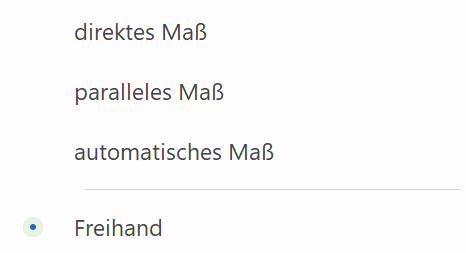
Nach Start der Funktion Vermassung neu erstellen können Sie die Richtung horizontal oder vertikal ändern, indem Sie den Cursor entsprechend positionieren (Hierbei erscheint eine temporäre optische Darstellung als Hilfe) oder aus dem Kontextmenü kann direktes, paralleles oder automatisches Mass gewählt werden. Die Optionen im Kontextmenü sind von die Positionierungsmethode derzeit ausgewählt abhängig (Beispiel unten verwendet Vertikal.)
Dimension parameters group
This field is only visible if a representation level has been activated.
![]() - Without parameter group
- Without parameter group
![]() - Parameter group 1
- Parameter group 1
![]() - Parameter group 2
- Parameter group 2
![]() - Parameter group 3
- Parameter group 3
The parameter group is a quick selection of preset types. If you select a parameter group, the associated parameter type is displayed. If you select "Without parameter group", the current settings are adopted.
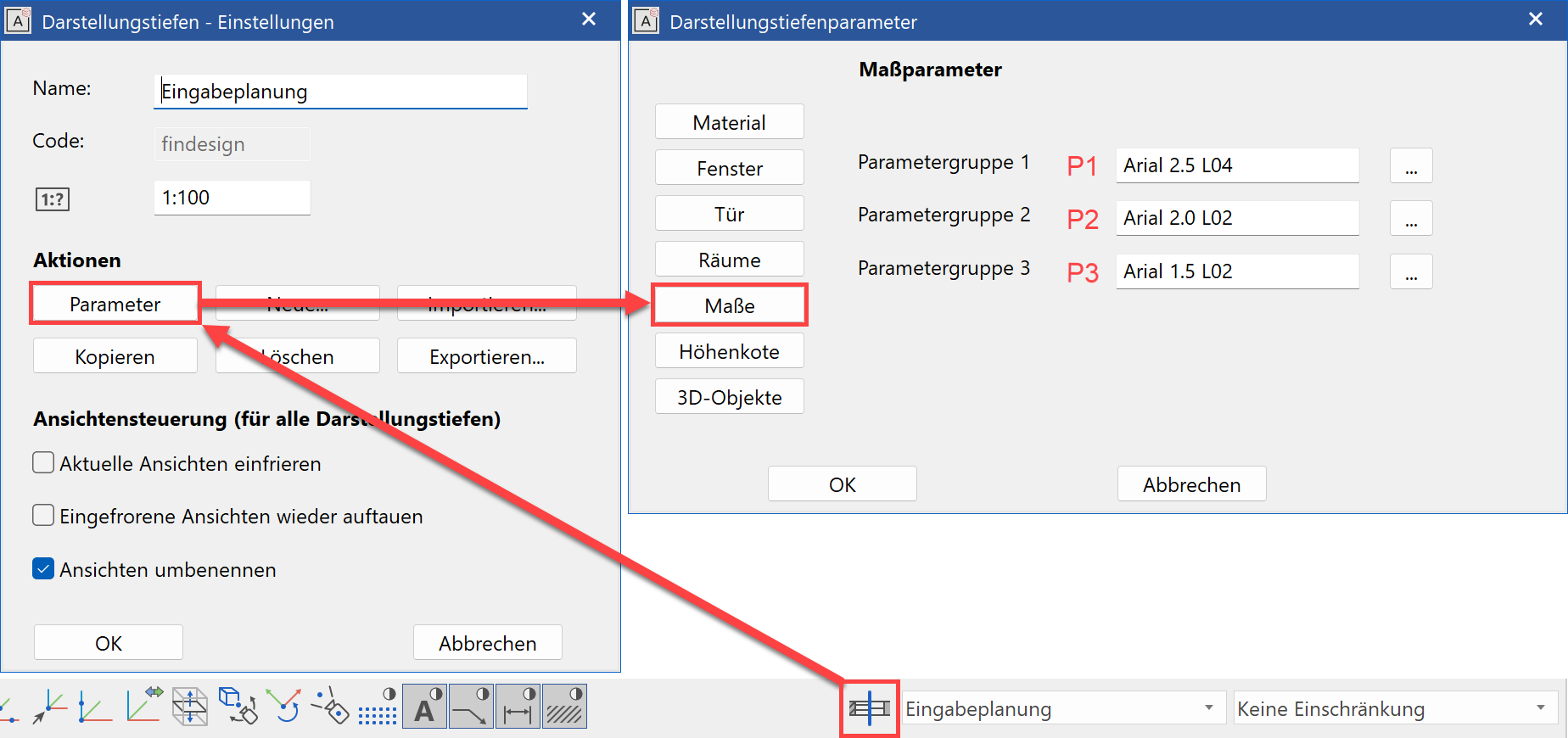
Parameter groups are assigned to individual parameter types for each representation level in the representation level parameters.
Parameter name
The "Parameter name" field displays all records. You can save additional records from the dimension parameter dialog window.
Font size
Use this field to change the font size of the dimension text. The superscript is enlarged proportionally to the main text.
### Dimension help line length You can determine the length of dimension help lines in one of two ways.
![]() - Fixed length of dimension help line
- Fixed length of dimension help line
![]() - Fixed distance to dimension point
- Fixed distance to dimension point
| Fixed length of dimension help line | Fixed distance to dimension point |
|---|---|


The distance is specified in paper millimetres.
Dimension limitation
You can select from various dimension demarcations.
![]() - without
- without
![]() - Arrow
- Arrow
![]() - Circle
- Circle
![]() - Slash, pen like dimension line
- Slash, pen like dimension line
![]() - Slash, pen configurable
- Slash, pen configurable
The dimensions are configured using the DIMENSION ARROW PARAMETERS detail parameter.
Dimension help line colour
 Adjust the colour of dimension help lines in this field.
Special character
![]()
If a SPECIAL CHARACTER option is activated, the selected character (diameter, square, arc, M or G) is added before the dimension figure. For a chain dimension, this option always applies to the entire chain. In the dimension parameters, you can specify whether to display a small or large diameter character under the DETAIL PARAMETERS menu > TEXT PARAMETERS.

Tip
If you only want to add a diameter character to one dimension figure, you can do this by editing the dimension figure after it has been added: Right-click dimension figure > Modify dimension text.
M,cm/mm dimensioning
The m,cm/mm dimensioning is a special depiction of the tolerance text for architectural dimension figures.
This rounds the millimetres to the nearest half centimetre and adds them in superscript. Metres are separated with a decimal point.

If a tolerance is switched on with the TOLERANCE function, m,cm/mm dimensioning is automatically deactivated.
Dimension on arc
![]()
The DIMENSION ON ARC function places the dimension point tangential to a circle or curve of your choosing. The function is only active once. You must select it again to use it another time.
Regenerate chain dimension
![]()
This function resets all dimension texts in a dimension chain that were moved by hand to their original positions.
Define dimension point
![]()
This function enables you to specify additional dimension points during editing. You may also add individual dimension points to a dimension chain that was created with a section line or opening dimension.
Delete dimension point
![]()
The function enables you, during creation or editing, to delete dimension points that have been placed. You can also delete individual dimension points that were created with a section line or an opening dimension.
Dimensioning options
![]() - Define section line for walls
- Define section line for walls
![]() - Define section line for wall contours
- Define section line for wall contours
![]() - Section line
- Section line
![]() - Define section line for axis grid
- Define section line for axis grid
![]() - Opening dimension/set definition line (size)
- Opening dimension/set definition line (size)
![]() - Opening dimension/set definition line (axis)
- Opening dimension/set definition line (axis)
To use a dimensioning option, you must select or click it. The same applies to all other dimensioning. The section or definition line is visible when editing a dimension chain. If such a dimension chain is copied into another storey, the new elements or windows are automatically dimensioned on the respective section or definition line. Certain modification actions automatically trigger a refresh via the REFRESH AR OBJECTS function so that the dimension chain recognises the new dimension points.
Define section line for walls
![]()
This dimensioning option is only available in ELITECAD Architecture and dimensions all walls with layers on a section line that were generated using the CREATE WALL function. Make sure that the section line is orthogonal (unless you prefer it otherwise). The section line must not go through the same point as the dimension chain.

Define section line for wall contours
![]()
This dimensioning option is only available in ELITECAD Architecture and dimensions all walls without layers on a section line that were generated using the CREATE WALL function. Make sure that the section line is orthogonal (unless you prefer it otherwise). The section line must not go through the same point as the dimension chain.

Section line
![]()
This dimensioning option is only available in ELITECAD Architecture and dimensions all elements on a section line. Make sure that the section line is orthogonal (unless you prefer it otherwise). The section line must not go through the same point as the dimension chain.

Define section line for axis grid
![]()
This dimensioning option is only available in ELITECAD Architecture and dimensions all axes on a section that were generated using the AXIS-GRID function in the AR OBJECTS menu. Make sure that the section line is orthogonal (unless you prefer it otherwise). The section line must not go through the same point as the dimension chain.

Opening dimension/set definition line (size)
![]()
This dimensioning option is only available in ELITECAD Architecture and dimensions all window, door and wall openings on a definition line. The definition line must lie on the exterior or interior surface of the wall, and the exterior or interior wall opening is dimensioned accordingly. For the opening width, the opening height is written under the dimension line.

Opening dimension/set definition line (axis)
![]()
This dimensioning option is only available in ELITECAD Architecture and dimensions all window and door axes on a definition line. The definition line must lie on the surface (exterior or interior) of a wall.

Opening dimension/parameter for opening dimension
![]()
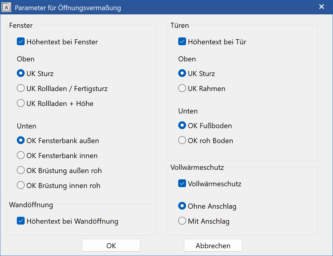
In this parameter dialog window, you can define in ELITECAD Architecture, which heights are to be dimensioned if definition line with sizes is used. There are separate value settings for windows and doors.
Tip
If the FULL HEAT INSULATION option is set, the dimension points react to the bare masonry itself and not to the insulation.
Delete section/definition line
![]()
This function is only available in ELITECAD Architecture and deletes a chain dimension's section line or definition line. This makes sense if a chain dimension consists of multiple section lines/definition lines.
Parameter for multi-layer dimensioning
![]()
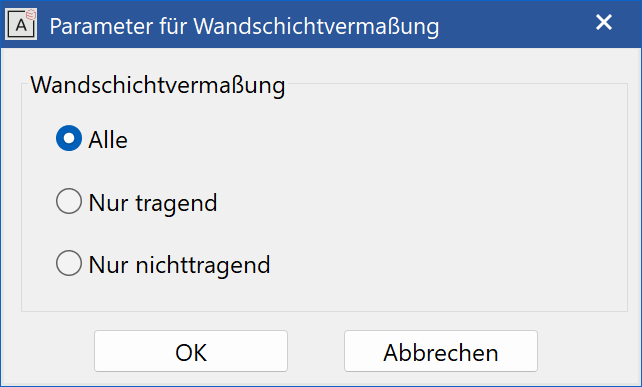
In this parameter dialog window, you can define which wall layers are to be dimensioned.
Auto dimensioning - single
Improved · 16 R1 · Improvements
![]()
This function is only available in ELITECAD architecture and creates all relevant dimensions for a selected contour. Current dimension parameters are used.
Auto dimensioning - multiple
Improved · 16 R1 · Improvements
![]()
This function is only available in ELITECAD architecture and creates all relevant dimensions for a selected contour. Up to three different dimension can be chosen in the dialog.
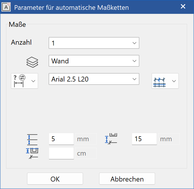
All settings are identical to the dimension selection in the function Create structure.


Dimension parameters
![]()
Opens the Dimension parameters dialog window.
Dimension positioning
![]() - Automatic
- Automatic
![]() - Horizontal
- Horizontal
![]() - Vertical
- Vertical
![]() - Direct
- Direct
![]() - Parallel
- Parallel
The dimension direction can be fixed: horizontal, vertical, automatic (horizontal and vertical) direct or parallel. The option parallel requires the indication of a line, which should be parallel to the dimension line.
After starting the Create new dimension function, you can change the direction horizontally or vertically by positioning the cursor accordingly (a temporary visual representation appears as a help) or direct, parallel or automatic dimension can be selected from the context menu. The options in the context menu depend on the positioning method currently selected (example below uses vertical.)
Dimension parameters group
This field is only available in ELITECAD Architecture and only visible if a representation level has been activated.
![]() - Without parameter group
- Without parameter group
![]() - Parameter group 1
- Parameter group 1
![]() - Parameter group 2
- Parameter group 2
![]() - Parameter group 3
- Parameter group 3
The parameter group is a quick selection of preset types. If you select a parameter group, the associated parameter type is displayed. If you select "Without parameter group", the current settings are adopted.
Parameter groups are assigned to individual parameter types for each representation level in the representation level parameters.
Parameter name
The "Parameter name" field displays all records. You can save additional records from the dimension parameter dialog window.
Font size
Use this field to change the font size of the dimension text. The superscript is enlarged proportionally to the main text.
Dimension limitation
You can select from various dimension demarcations.
![]() - without
- without
![]() - Arrow
- Arrow
![]() - Circle
- Circle
![]() - Slash, pen like dimension line
- Slash, pen like dimension line
![]() - Slash, pen configurable
- Slash, pen configurable
The dimensions are configured using the DIMENSION ARROW PARAMETERS detail parameter.
Dimension help line colour
Adjust the colour of dimension help lines in this field.
Special character
![]()
If a SPECIAL CHARACTER option is activated, the selected character (diameter, square, arc, M or G) is added before the dimension figure. For a chain dimension, this option always applies to the entire chain. In the dimension parameters, you can specify whether to display a small or large diameter character under the DETAIL PARAMETERS menu > TEXT PARAMETERS.
When dimensioning thread diameters in ELITECAD Mechanics these dimensions are recognised and the letters M and G will be added automatically, provided, that the thread has been created with the drill/sink functions of ELITECAD.
Tip
If you only want to add a diameter character to one dimension figure, you can do this by editing the dimension figure after it has been added: Right-click dimension figure > Modify dimension text.
Tolerance (not available for chain dimension)
Here, enter how the tolerance text should be displayed. If the tolerance text is switched on, m,cm/mm dimensioning is automatically switched off.
![]() The tolerance text is not displayed.
The tolerance text is not displayed.
![]() Having set the dimension line, the tolerance text is requested.
Having set the dimension line, the tolerance text is requested.
![]() Having set the dimension line, the lower and upper tolerance text is requested.
Having set the dimension line, the lower and upper tolerance text is requested.
![]() Having set the dimension line, the lower and upper tolerance text is requested and integrated into the dimension text.
Having set the dimension line, the lower and upper tolerance text is requested and integrated into the dimension text.
Dimension on arc
![]()
The DIMENSION ON ARC function places the dimension point tangential to a circle or curve of your choosing. The function is only active once. You must select it again to use it another time.
Regenerate chain dimension
![]()
This function resets all dimension texts in a dimension chain that were moved by hand to their original positions.
Define dimension point
![]()
This function enables you to specify additional dimension points during editing. You may also add individual dimension points to a dimension chain that was created with a section line or opening dimension.
Delete dimension point
![]()
The function enables you, during creation or editing, to delete dimension points that have been placed. You can also delete individual dimension points that were created with a section line or an opening dimension.