Height Marker
Specify height marker
|
|
Toolbar * Create new |
| Lay-out menu > Dimensions > Height marker |
The HEIGHT MARKER function can be found among the dimension functions.
Height marker dimensioning places a symbol for which the height is always automatically calculated. Usually, the height position is calculated from the coordinate origin (X0, Y0 = format middle).
The symbol can be changed as desired.
Set levels
To launch it, click the HEIGHT MARKER function.
Dimension which point?
On the plan, enter the point that you would like to dimension with a height marker.
Position of height marker
You can only move horizontally to the point at which the marker should be placed. You can also move the cursor to a pre-existing height marker to align the new marker to it. Finally, you can define the marker's position by flipping it.

Associations
A marker that is placed in a view or section linked with the design model is retained if changes are made to the geometry. After the view/section is refreshed, the height marker is recalculated.
Edit/modify text
You can edit the marker's text in the element part selection mode (Alt key).
Height marker property bar

Height marker parameter
![]()
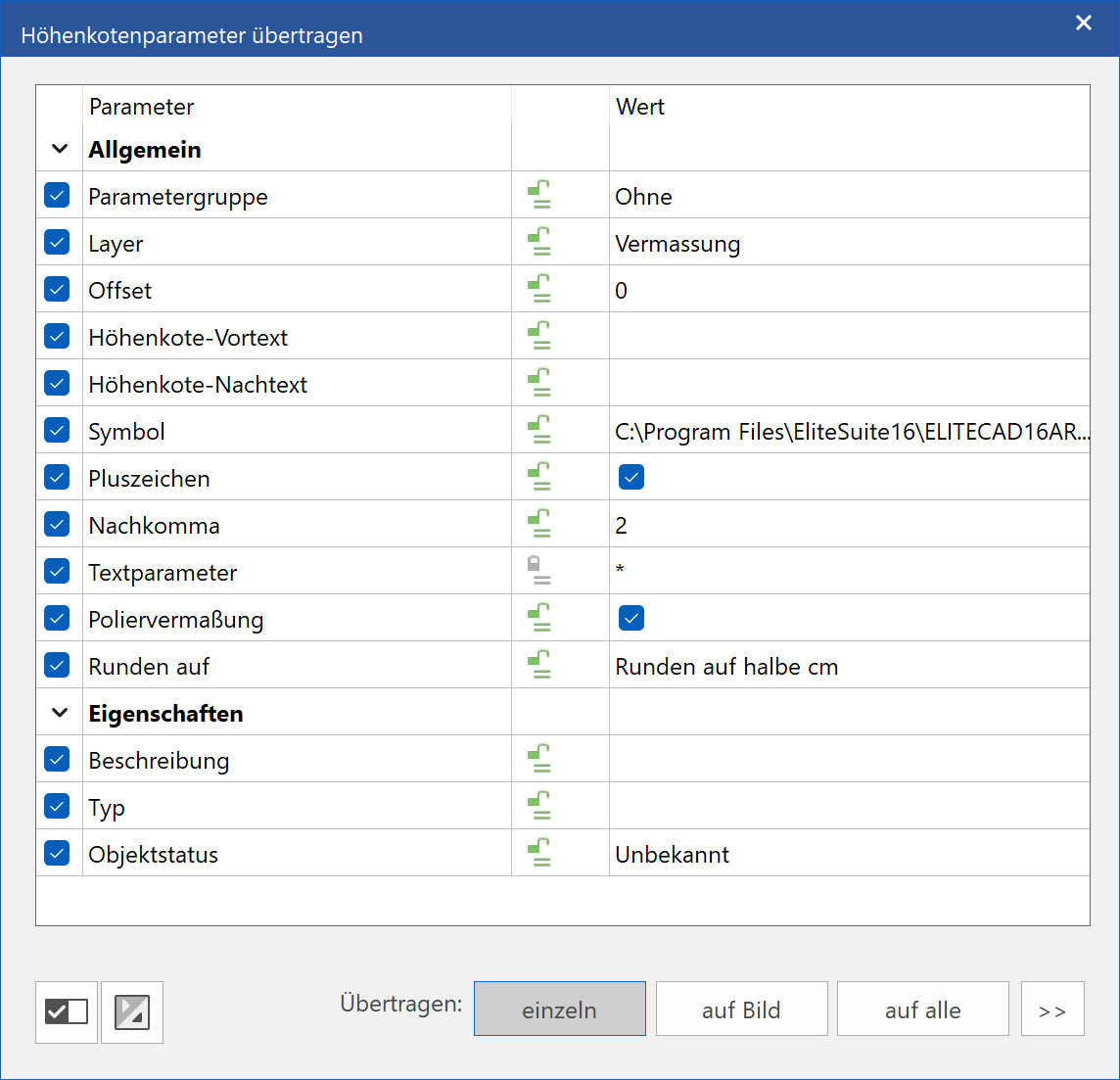
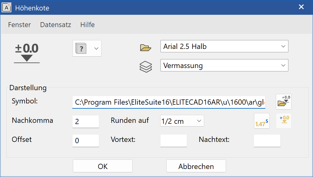
In the height marker parameters, height marker settings are configured. You can select the symbol for the height marker and you can configure how it will be depicted.
General parameters
 Renovation planning state (only in ELITECAD Architecture)
 Freeze (only in ELITECAD Architecture)
 Type
Type Layer (name of the record)
The general parameters for objects are described in chapter Renovation planning.
Parameters group
Improved · 16 R1 · Improvements
This field is only visible if a representation level has been activated.
![]() - Without parameter group
- Without parameter group
![]() - Parameter group 1
- Parameter group 1
![]() - Parameter group 2
- Parameter group 2
![]() - Parameter group 3
- Parameter group 3
The parameter group is a quick selection of preset types. If you select a parameter group, the associated parameter type is displayed. If you select "Without parameter group", the current settings are adopted.
Parameter groups are assigned to individual parameter types for each representation level in the representation level parameters.
Symbol
![]()
The symbol that should be used to create the marker is selected here. You can select the file directly using the selection button.
The standard path for symbols is:
<ELITECAD installation path>\u\<version>\<ar|me>\glob\symbol\...
Own symbols
You can create as many of your own symbols as you like. Important: The reference point for each symbol should always be on the arrow tip, as that is the point from which the height is calculated.
Examples:

Tip
If you would like to create a symbol of your own, it is best to load a template from the path listed above, adapt it as you wish, and save it under a new name.
Offset
Using the offset, a reference level other than the coordinate origin can be set and used to place the height marker. This new level is measured relative to the coordinate origin using the currently set unit.
The option is needed if a part is cut for space reasons in a detail section, for instance.
Tip
The value matches the one in the property bar.
Height marker – Offset over point
![]()
Instead of a manual entry for the offset, you can specify a point digitally with the mouse. The measured height from the coordinate origin is entered into the "Offset" field and the height of the marker is recalculated.
Height marker – Offset

Using the offset, a reference level other than the coordinate origin can be set and used to place the height marker. This new level is measured relative to the coordinate origin using the currently set unit.
Height marker – Leading text/Trailing text

You can enter additional text in these fields to be added to the calculated height text.
Plus sign
![]()
This setting is used to add a plus sign as a pre-text before the value.
M,cm/mm dimensioning
![]()
The m,cm/mm dimensioning is only available in ELITECAD Architecture and writes the millimetres in superscript. In the height marker parameters, you can configure rounding to the nearest half centimetre or nearest millimetre. When m,cm/mm dimensioning is activated, the number of decimal places is irrelevant for height marker parameters.
Modify height marker over polygon
![]()
Using this function, you can modify the offset of multiple markers at the same time.
After selecting this function, place a polygon over the markers to be changed. Next, enter the offset for these markers in the entry line. The entry is always entered in the current unit and must be confirmed with Enter .
Modify height marker via copy parameters
![]()
If a marker is clicked after the COPY PARAMETERS function, there are additional options available for global modifications.