Machining Symbols
Drill symbols
|
|
Lay-out toolbar |
| Lay-out menu > Symbols > Drill symbols |
Drilling symbols are mainly used in steel construction as well as in sheet metal and metal processing. The diameter of the intended screw connection with the associated through hole is displayed with standardized symbols. Additional symbols also indicate whether the screwing or drilling is carried out in the workshop or during final assembly.
After activating the function, the window with the following selection appears.

If you place the mouse pointer over a symbol, the correct use of this symbol is indicated by a tooltip.
The selection is made with the mouse and can be placed in the drawing in conjunction with the cursor snap functions.
Surface symbols
|
|
Lay-out toolbar |
| Lay-out menu > Symbols > Surface symbols |
By entering surface symbols in construction drawings, the designer defines the surface properties of components. In addition, with symbol additions, manufacturing processes, machining direction, etc. can also be specified.
![]()
Once defined using SAVE RECORD, the settings can be saved under any name for future use.
Predefined settings can be accessed from the TEXT > PARAMETERS selection menu. The text parameter dialog is opened by clicking on the text parameter button. New parameter sets can then be created in this.
After activating the function, the input dialog appears:
![]()
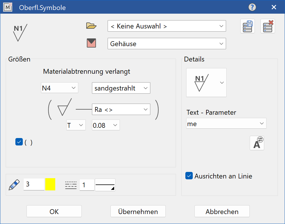

On the right side of the input dialog, select the required specification from the selection offered. You can choose from the following groups of symbols:
![]() Surface symbols according to DIN 140
Surface symbols according to DIN 140
![]() Surface symbols according to DIN ISO 1302, if machine processing is required
Surface symbols according to DIN ISO 1302, if machine processing is required
![]() Surface symbols according to DIN ISO 1302, if machine processing is optional
Surface symbols according to DIN ISO 1302, if machine processing is optional
![]() Surface symbols according to DIN ISO 1302, if machine processing is prohibited
Surface symbols according to DIN ISO 1302, if machine processing is prohibited
On the left side of the input dialog, you will find the fields for the information of:
- specification of the roughness grade or roughness value
- all common processing methods and technical surface properties
- Machining allowance
- Groove direction
- Reference route
If you select FREE INPUT in the MACHINING PROCESS input field, company-specific special processes can be entered in the drawing.
If you decide on the surface symbols according to DIN 140, the input dialog changes as follows:
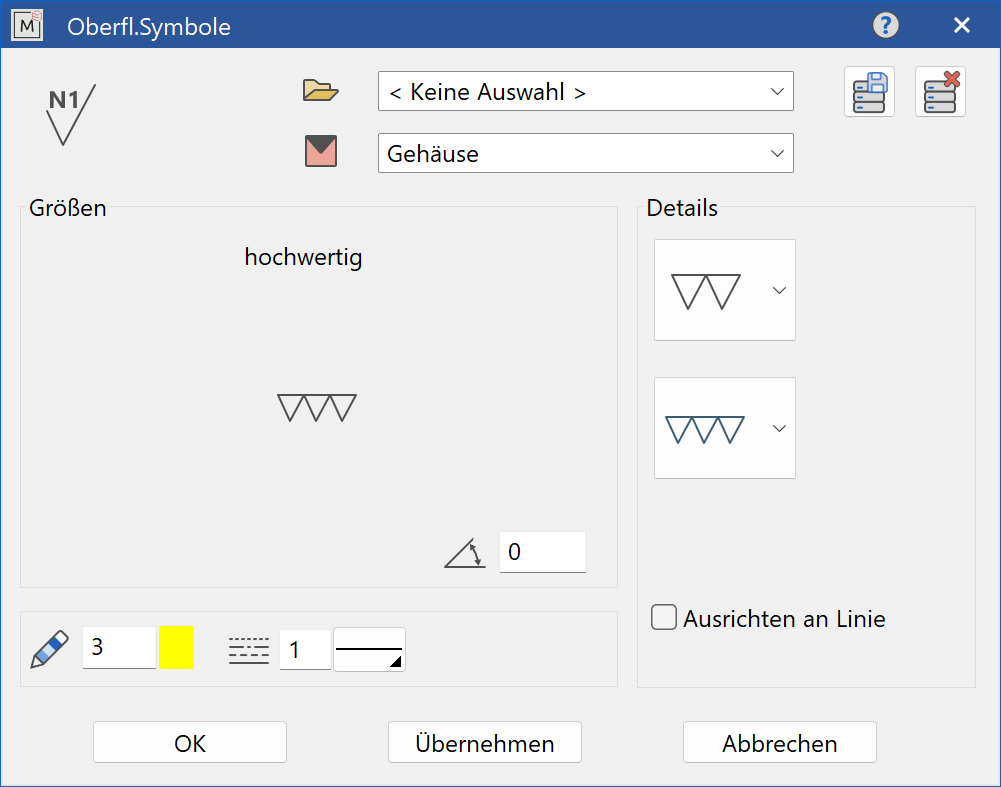
In the right input window, select the processing class in the second selection field:
- Plain
- Rough
- Middle Grade (Middle machining)
- Fine (Grinding)
- High grade (Super finishing)
The other input fields mean:
 Pen number for the contour lines
 Line type for the contour lines
Symbol is positioned accordingly by clicking on a line.
Positioning side (above / below the line) is done with the mouse.
Close the function with a final click of the mouse.
The completed dialog is confirmed with  . This means that the surface symbol is dynamically active at the cursor for positioning in the drawing. The reference point is the lower tip of the symbol.
The function is ended when it is positioned within the construction.
. This means that the surface symbol is dynamically active at the cursor for positioning in the drawing. The reference point is the lower tip of the symbol.
The function is ended when it is positioned within the construction.
The function can be opened repeatedly for other identical surface symbols. The last input parameters are retained and are suggested the next time it is opened.
![]() Always use the MODIFY > ME OBJECTS function to change the surface symbols.
Always use the MODIFY > ME OBJECTS function to change the surface symbols.
Technical notes
|
|
Lay-out toolbar |
| Lay-out menu > Symbols > Technical notes |
The technical notes support the finishing of drawings.
After activating the function, the selection window appears.
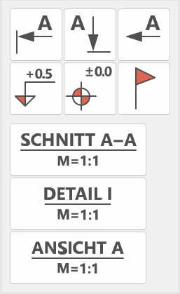
Now select the symbols for section designations, annotations or elevation marks.
The selection is made with the mouse and can be placed in the drawing in using the cursor snap functions.
Manipulations such as rotating, mirroring, scaling, etc. can also be used.
These symbols can be adapted in size and shape to align to your company standard.
You will find the associated library files in the installation directory under
<ELITECAD-installation path>\u\<version>\me\symbols\sf\l\ - under the file names obfl181 to obfl189.
However, changes to these files should only be made in consultation with your system administrator.
Welding symbols
|
|
Lay-out toolbar |
| Lay-out menu > Symbols > Welding symbols |
Welding symbols are an essential part of construction drawings of welded components.
With standardized symbols according to DIN 1912, the designer defines the preparation and execution of welded joints. At the same time, this symbolism also defines the preparation of the weld seam, such as the joint shape according to DIN 2559 (steel pipes) or DIN 8551 (steel sheets), etc.
After activating the function, the input dialog appears:
![]()
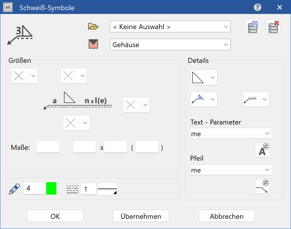
The general input fields mean:
![]() Selection menu for the basic symbol. Seams welded on one or both sides can be selected.
Selection menu for the basic symbol. Seams welded on one or both sides can be selected.
![]() Side of the basic symbol (only for seams welded on one side)
Side of the basic symbol (only for seams welded on one side)
![]() Side of the reference line (only for seams welded on one side)
Side of the reference line (only for seams welded on one side)
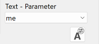 This selection menu enables access to already defined text parameters. The text parameter window is opened by clicking on the text parameter button. New parameter sets can then be created in this.
![]() This selection menu enables access to arrow parameters that have already been defined. The arrow parameter window is opened by clicking on the arrow parameter button. New parameter sets can then be created in this.
This selection menu enables access to arrow parameters that have already been defined. The arrow parameter window is opened by clicking on the arrow parameter button. New parameter sets can then be created in this.
 Pen number for the contour lines
Line type for the contour lines
The options for the additional symbols differ between seams welded on one side and on both sides.
Seams welded on one side
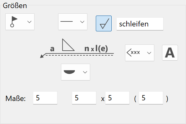
Meaning of the input fields:
![]() Supplement symbol
Supplement symbol
![]() Additional symbol for the seam design
Additional symbol for the seam design
![]() If a symbol has been selected for the seam execution, you can specify an additional processing of the seam. Text entry is optional.
If a symbol has been selected for the seam execution, you can specify an additional processing of the seam. Text entry is optional.
![]() Opposite seam
Opposite seam
![]() Supplementary information (welding process, ...)
Supplementary information (welding process, ...)
![]() Text entry for the supplementary information
Text entry for the supplementary information

Enter the dimensions in sequence:
Weld seam thickness (a)
Number of weld seams (n)
Weld seam length (l)
Distance between the welds seams (e)
Seams welded on both sides
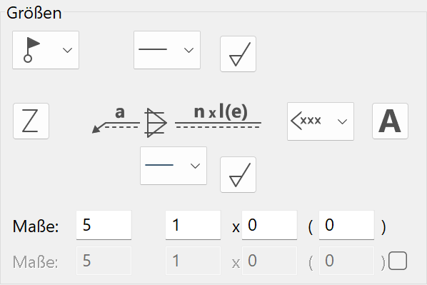
In the case of seams welded on both sides, different additional symbols for the seam design can be selected for both sides. Furthermore, the dimensions can also be done differently. In order to activate the second line for the dimensioning, the check box must be activated:

More functions:
![]() If a two-sided weld is active, an offset symbol appears.
If a two-sided weld is active, an offset symbol appears.
The remaining input fields behave in the same way as for the seams welded on one side.
Geometric tolerances
|
|
Lay-out toolbar |
| Lay-out menu > Symbols > Geometric tolerances |
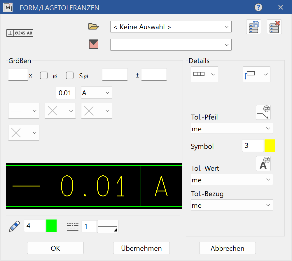
This function is used to create a construction drawing with geometric tolerances in accordance with DIN ISO 1101.
After activating the function, the input dialog appears:
![]()
![]()
Once defined using SAVE RECORD, settings can be saved under any name for future use.
Predefined settings can be accessed from the selection menus TOL. ARROW, TOL. VALUE, TOL. REFERENCE. The associated parameter buttons open the respective parameter window. New parameter sets can then be created.
Define the symbols and values for your construction:
![]()
![]()
![]()
![]() Tolerance frames with 2, 3, 4 or 5 fields can be selected.
Tolerance frames with 2, 3, 4 or 5 fields can be selected.
![]()
![]()
![]()
![]() The dropdown menu next to that is used to select the representation for the intended positioning of the tolerance frame with the reference arrow for the element with tolerance on the drawing.
The dropdown menu next to that is used to select the representation for the intended positioning of the tolerance frame with the reference arrow for the element with tolerance on the drawing.
The geometric properties of the shape associated with the tolerance can be selected using a corresponding symbol in the first field of the tolerance frame.
![]() Straightness
Straightness
![]() Evenness
Evenness
![]() Roundness ( circular shape )
Roundness ( circular shape )
![]() Cylindrical
Cylindrical
![]() Line shape
Line shape
![]() Plane shape
Plane shape
![]() Parallelism
Parallelism
![]() Rectangularity
Rectangularity
![]() Inclination
Inclination
![]() Position
Position
![]() Concentricity and coaxiality
Concentricity and coaxiality
![]() Symmetry
Symmetry
![]() Circular runout (often referred to simply as Runout)
Circular runout (often referred to simply as Runout)
![]() Total runout
Total runout
The tolerance value is entered in the second field of the tolerance frame. In the case of circular, cylindrical or spherical tolerance zones, the symbol ø or Sø is placed in front of the tolerance value when the symbol ø or Sø is activated.
The letter indicating the reference is entered in the 3rd, 4th and 5th fields of the tolerance range. Possible references are A, B, C, D, A-B and A-C.
Additional features can be selected for each reference using a corresponding symbol.
![]() Projected tolerance zone
Projected tolerance zone
![]() Maximum material condition
Maximum material condition
![]() Least material condition
Least material condition
![]() Free state requirement (non-dimensionally rigid parts)
Free state requirement (non-dimensionally rigid parts)
![]() Envelope requirements
Envelope requirements
![]() Common zone
Common zone
![]() Inside diameter (Low diameter)
Inside diameter (Low diameter)
![]() Outside diameter (Maximum diameter)
Outside diameter (Maximum diameter)
![]() Pitch diameter
Pitch diameter
![]() Line element
Line element
![]() Not convex
Not convex
![]() Any cross-section
Any cross-section
The number of elements for which the tolerance is valid can be entered above the tolerance frame, which in turn can be supplemented with your own size and tolerance information.

A further feature to describe the element within the tolerance zone can be specified under the tolerance frame.
The display for diameter or circle diameter is controlled by the following check boxes:
Diameter
 Circle diameter
The input fields at the bottom of the dialog adjust the depiction:
Pen number for the contour lines
Line type for the contour lines
The right-hand input fields of the dialog have further formatting options:
![]() Representation for the tolerance arrow
Representation for the tolerance arrow
 Pen number for the tolerance symbol
 Representation for the tolerance value
 Representation for the tolerance references
The completed dialog is confirmed with . This makes the symbol dynamically active at the cursor for positioning in the drawing.
After placing it on the desired position, the reference arrow is indicated with 2 cursor positions up to the element with these tolerances.
The function is ended when the finished reference arrow is displayed.
![]() By selecting a single tolerance frame, you can switch to the additional symbol for identifying the reference with a letter.
By selecting a single tolerance frame, you can switch to the additional symbol for identifying the reference with a letter.
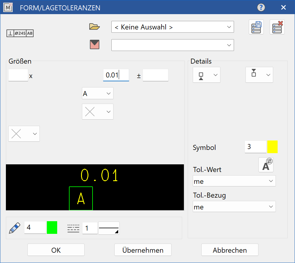
The switch on the right allows you to select the position of the reference symbol in the drawing.
![]()
![]()
![]()
![]()
The meaning of all other input fields of the dialog is the same as that of the tolerance frames with 2, 3, 4 or 5 fields, as described above.
The completed dialog is confirmed with . This makes the symbol dynamically active at the cursor for positioning in the drawing.
After placing it on the desired position, the representation of the reference arrow is indicated with 1 cursor positions up to the element with these tolerances.
The function is ended when the finished reference arrow is displayed.
![]() Always use the MODIFY > ME OBJECTS function to change geometrical tolerances.
Always use the MODIFY > ME OBJECTS function to change geometrical tolerances.
Edge tolerance
|
|
Lay-out toolbar |
| Lay-out menu > Symbols > Edge tolerance |
The edge tolerance dialog offers the option of inserting information about work piece edges in accordance with DIN 6784 in the drawing.
After activating the function, the input dialog appears:
![]()

![]()
Once defined using SAVE RECORD, settings can be saved under any name for future use.
Predefined settings can be accessed from, the TOL.-ARROW and TOL.-VALUE selection menus. The associated parameter buttons open the respective parameter window. New parameter sets can then be created.
The menu on the right allows you to select the position of the edge symbol for display in the drawing.
![]()
![]()
![]()
![]()
The edge dimensions are selected in the central input fields, where 2.5, 1.0, 0.5, 0.3 and 0.1 for edges with burrs, 0.05, 0.02, -0.02 and -0.05 for sharp edges and -0.1, -0.3, -0.5, -1.0 and -2.5 stands for burr-free edges or undercuts. With the selection of free, self-defined edge dimensions are possible.
The input fields at the bottom of the dialog adjust the depiction:
 Pen number for the contour lines
Line type for the contour lines
The right-hand input fields of the dialog have further formatting options:
![]() Depiction of the tolerance arrow
Depiction of the tolerance arrow
Depiction of the tolerance value
The completed dialog is confirmed with . This makes the symbol dynamically active at the cursor for positioning in the drawing.
After placing it on the desired position, the depiction of the reference arrow is indicated with 2 cursor positions up to the element with these tolerances.
The function is ended when the finished reference arrow is displayed.