Tolerances
|
|
Toolbar > Tolerances |
| Lay-out menu > Tolerances |
If components are to be assembled without reworking, production must be allowed a certain deviation from the nominal dimension (tolerance). With your information in drawings, designers decide on the permissible manufacturing tolerances. The size of the permissible tolerance depends on the function of the components. They also influence the quality of products and their lifespan.
The size of the tolerance is also a decisive factor in the selection of the relevant manufacturing process. In order to keep the manufacturing costs in check, unnecessarily narrow tolerances typically should be avoided.
General tolerances
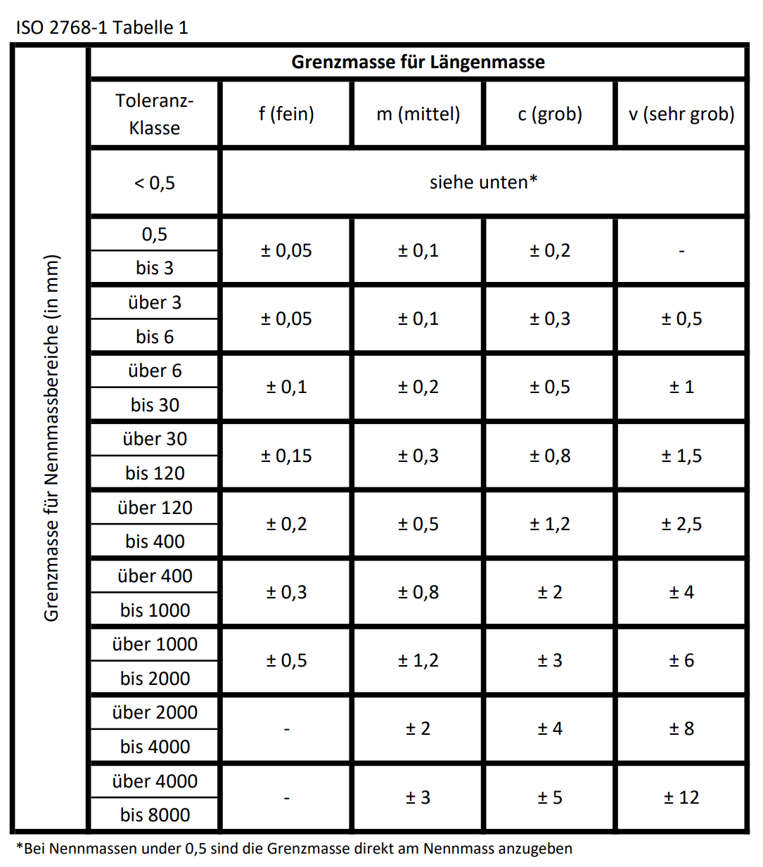
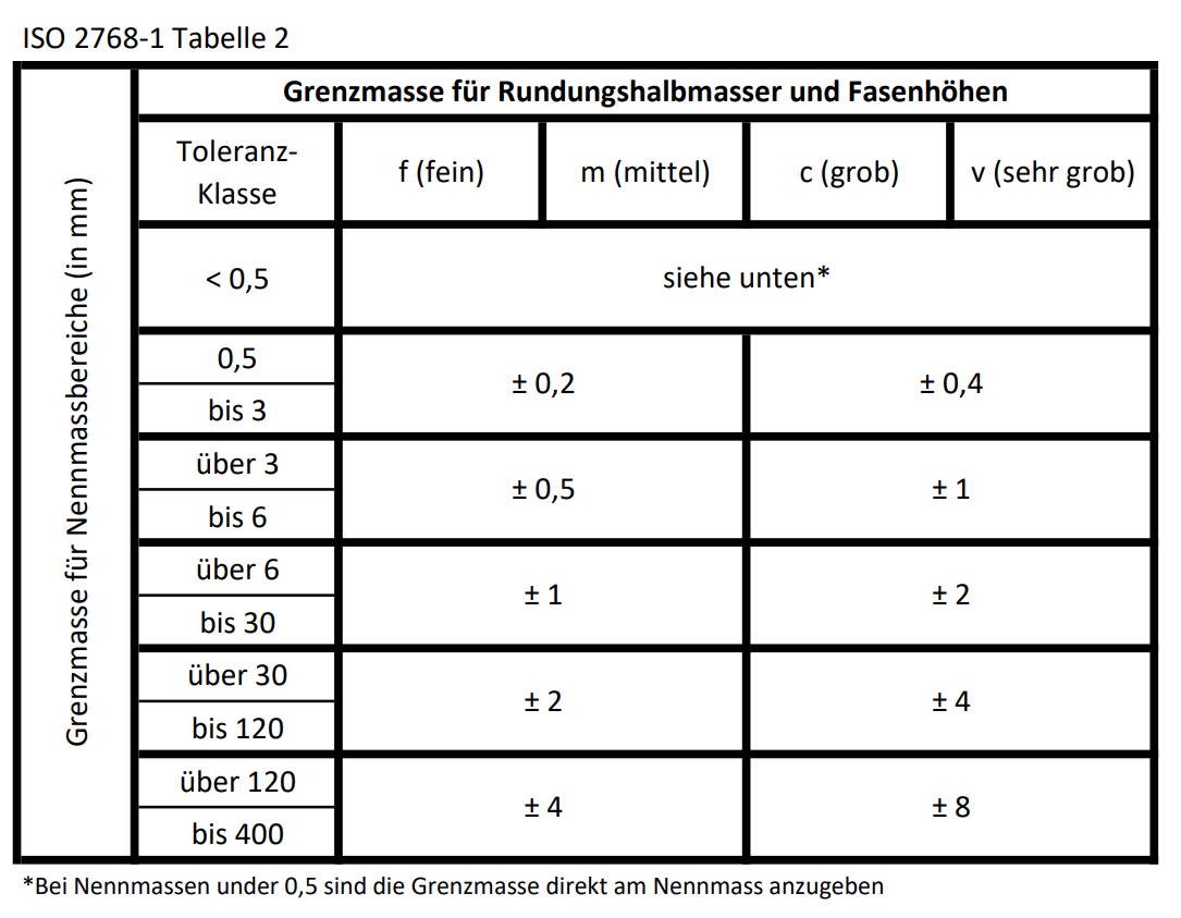
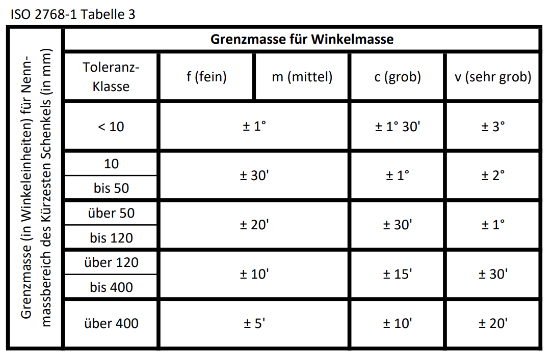
For all dimensions without tolerance specifications, the permissible tolerances are regulated in the General tolerances according to DIN ISO 2768 (free dimension tolerances).
Separate tables for linear dimensions and for angular dimensions provide information on the permissible deviations from the nominal dimensions.
The selection of the tolerance class is often based on the current standard of your company and in many cases occurs alongside of the production.
Information about the applicable standard and the selected tolerance class is placed as a note in the title block or in the area of the title block on the drawing.
Tolerance table
|
|
Lay-out menu > Tolerances |
| Lay-out menu > Tolerances > Tolerance table |
If the tolerances according to the general dimensional tolerances for the component function are not permissible (too large), the designer must enter additional information in the drawing. The nominal dimension is given a tolerance specification = deviation.

These dimensions (upper tolerance and lower tolerance) result in two limiting dimensions, the maximum dimension and the minimum dimension.
The tolerance table, if it is in the drawing, is updated every time it is opened. It is deleted if there are no more dimensions with tolerance values in the drawing.
Fittings table
|
|
Lay-out menu > Tolerances |
| Lay-out menu > Tolerances > Fittings table |
For exact component pairings with guaranteed properties such as:
Shaft-hub connections
Bearing seats
Plain bearing pairings
Linear guides
etc.
fits with ISO abbreviations are used.
The nominal dimension is given a code as an addition - e.g. 50 H7.
However, these abbreviations may not be used for shoulder dimensions and for hole centre distances.
All ISO abbreviations are assigned dimensions (upper tolerance and lower tolerance) depending on the nominal dimension range in standard tables. This creates two limit dimensions, maximum dimension and the minimum dimension.
Fittings proposal
|
|
Lay-out menu > Tolerances |
| Lay-out menu > Tolerances > Fittings proposal |
For a technically correct fit selection, precise information for the designer about the limiting dimensions of the selected nominal dimension dependent tolerance fields is necessary.
Depending on the factory standards and manufacturing options, the choice of fit is made for the system based on a standard shaft or a standard bore.
As a rule, fit information for bores and internal dimensions are shown with capital letters and fit information for shafts and external dimensions with lower case letters.
In the relevant standards you will find preferred combinations of fits for various functions and applications.
The process of choosing a fit can be broken down into the following points:
- Choice of fit system
- Choice of fit series
- Type of fit
- Consideration of various aspects
Choice of fit system
With the fitting systems, a distinction is made between a Standard drill and a Standard shaft.
Shaft is used as the term for all external dimensions between two parallel planar surfaces of a work piece or parallel tangent planes on round work pieces.
Drill is used as the term for all internal dimensions.
The standard drill system is preferred (suggested as the default value). Exceptions are economic aspects, e.g. if several parts are mounted on the same shaft, it is more economical to manufacture the shaft according to a tolerance than to vary the tolerances of the various bores.
Choice of the fit series
There is a preferred fit series (series 1) and a supplementary fit series (series 2) to limit the number of tools to be used. The choice of the series is not offered, but can be labelled as a characteristic.
Type of fit
Each tolerance has a maximum dimension and a minimum dimension, which form the limiting dimensions range within which the actual dimension must lie. The combination of the largest and smallest dimensions of two work pieces to be paired results in a dimensional difference, which is called fit and can be divided into 3 types:
Loose fit
Loose fit is also known as a "Clearance fit". Occurs when there is always clearance between the paired parts. The shaft is always smaller than the bore.
Tight fit
Tight fit is also known as a "Press fit". Occurs when there is always an oversize between the paired parts. The shaft is always larger than the bore.
Transition fit
Transition fit is also known as a "Snug fit". Occurs when the actual dimensions allow both clearance and oversize. The default value is the clearance fit.
Various points of view
Serve for the specific selection of a fit with the help of:
Features.
General use cases.
Sample cases.
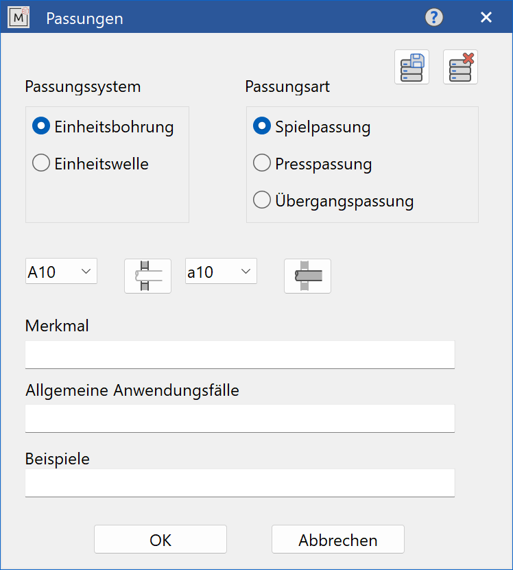
When the function is opened, the input dialog appears:
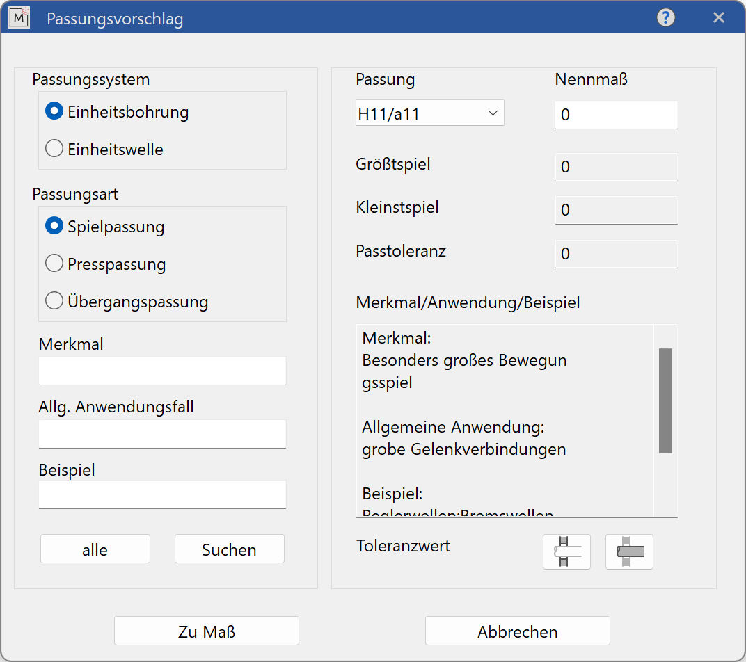
The selection of the suggested fit is made through the choice of the Fit system, the Fit type and, optionally, the Fit series (selected using features). The list of possible fits can be further restricted by entering search terms for the various aspects in one or more input fields. There is one word in each case, which occurs in the respective characteristics (upper and lower case letters are not recognised). An empty input field means that there is no restriction from this field. Individual strings (search criteria) must be separated by a semicolon ”;“. Only matches are displayed in which all search strings occur ("logical AND").

The result is a drop-down list populated only with the possible Fit series. After selecting a fit from this list and specifying a nominal size, the fitting dimensions are calculated and displayed.
Depending on the selected Fit type, the Upper dimension, Lower dimension, Largest dimension, Smallest dimension are displayed. The Fit tolerance is displayed for all fit types . This value indicates the possible fluctuation of the clearance or oversize.
In addition, all Characteristics, General applications, Examples are output in a text field.
![]()
![]()
The tolerance values for the bore and shaft can be displayed in a separate dialog by pressing the corresponding button.
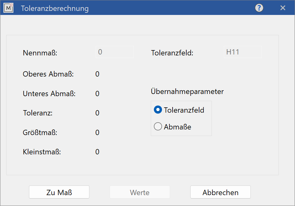
The button Values calculates and displays the corresponding values for the entered nominal dimension over the specified tolerance.
The tolerance can be added to a dimension using the To dimension button. The dimension is selected with a click, the dimension text consists of the tolerance field or the dimensions, depending on the selected copy parameters.
Fit manager
|
|
Lay-out menu > Tolerances |
| Lay-out menu > Tolerances > | Lay-out menu > Tolerances > Fits management |
When the function is opened, the input dialog appears:
The defined fits are permanently saved as data records in a file. The data records can be entered again, changed or deleted.
The first step is to select the Fit system. The default value is Standard bore. The Fit type is also selected. The default value is Clearance fit.
The basis of a fit is the selection of tolerances for the bore and the shaft from the lists.
![]()
![]()
These buttons take you back to the tolerance calculation dialog.
When saving, a check is made whether the data record already exists. That means, if a record was loaded and then something changed in the text fields, it will be overwritten. Otherwise a new record is created.
A data record is identified by its tolerance values and the fit type. The fit system can be recognized by the letters of the tolerances (capital letters for the bore = Standard drill, capital letters for the shaft = Standard shaft).
A data record can, of course, also be deleted from the menu.
![]()
The characteristics for the fit are entered in the relevant text fields. If there are several values for a type, they can be separated by a semicolon ”;”.