Layer

Layers are the preferred method to structure plans in ELITECAD Architecture. The Layer manager is described with examples from ELITECAD Architecture.
ELITECAD Mechanics offers multiple tools to structure objects in a drawing. The classification structure (with model/group/class/level), the layer structure and the hierarchical assembly groups.
The classification structure is the preferred method to structure plans in ELITECAD Mechanics. The Classification manager is described with examples from ELITECAD Mechanics.
Active layer

The current layer is displayed in this field. The program recognises the current layer for the 2D-elements (elements, text, hatch) for dimensioning and for each construction part.
If you have made a selection on the screen, you can modify the structure by selecting a different layer.
The layers switched off in the layer manager are not displayed in the selection.
State layer for objects
The architecture objects (walls, ceilings, windows, etc.) are automatically assigned a layer as this can be entered directly in the parameter dialog window.
The layer can be selected or saved with the correct layer in the parameter record in the "Layer" field.
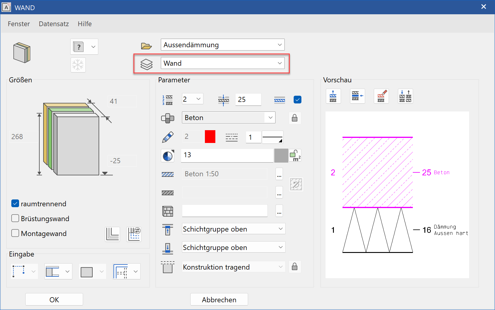
If a parameter record is selected in the wall property bar, the layer converts automatically to the layer saved in the parameter.

Layer manager
|
|
Window toolbar, Layer toolbar |
| Window menu > Layer |
![]()
The layer manager opens with a single click on the LAYER function.
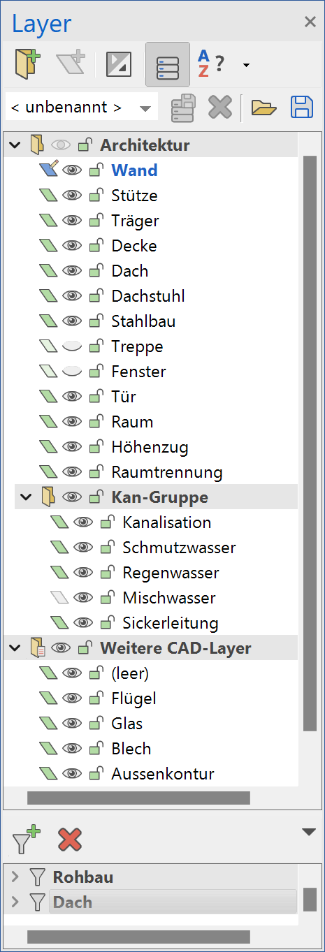
Header functions
The top row populated with functions in the manager window.
Structure
The layers are structured into main layer groups and layer groups.
In this example:
Main layer group > "Architecture"
Layer group > "Drainage group"
DXF layer
Layers made up of data imported via the DXF/DWG interface are stored in this group.
Further CAD layers
If data is inserted from other ELITECAD design models with layers that are not defined in this project, these layers are stored in the main group "Further CAD layers".
If a layer is deleted from the default structure that still contains data, the layer is then added to the Further CAD layers group.
These layers are only listed as long they contain data.
Filter
A filter is an instrument used for switching a certain subset of layers to visible, invisible or visible alone.
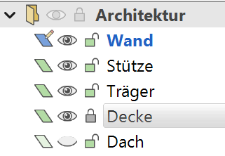
Meaning of the symbols in layer manager
 |
|
|---|---|
| Layer main group/layer group | |
| Layer without content (as long no objects assigned to this layer) | |
| Layer with content (objects have already been assigned to this layer) | |
| Layer is active | |
| Layer is visible | |
| Layer is invisible | |
| Layer is locked | |
| Layer is unlocked | |
 |
|
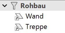
| Filter | |
| Layer in filter |
Visibility
The "eye" indicates whether a layer is visible or invisible. The active layer is always visible.
Lock layer
Locked layers may NOT be edited. The capture points can still be selected, however. The active layer cannot be locked.
The pen colour with which the locked layers are displayed is specified under SETTINGS > OPTIONS > REFERENCE PLAN.
Select multiple layers
Multiple individual layers can be selected with the Ctrl key. A specific area can be selected with the Shift key or an area opened up with the cursor.
Layer manager header functions

New group
![]()
Layers can be combined into a group for the sake of clarity. The function creates a layer group at the end of the list. The name can immediately be edited.
New layer
![]()
Creates a new layer. The name can immediately be edited. The insert location depends on the Sorting. The layer is created at the end of the list for "user-defined" sorting.
Expand/close all layer groups
Using this switch all layer groups can be expanded or collapsed at once.
Manage/save record
This function shows a second row with record management functions in the header functions.
Manage records in the parameters

Records with layer structures can be saved, loaded or deleted in the parameters. These records are written to the local parameters.
Import/export records
Records with layer structures can be saved, loaded or deleted in the parameters. These records are written to the local parameters.
Sort
User-defined sorting
The order of the layers can be freely defined by moving the layers. If new layers are created in the alphabetical sorting, these are listed in the "user-defined" sorting at the end of the list.
Ascending/descending sorting
The layers are listed alphabetically.
Layer manager context menus
There are two context menus in the layer manager (right-click). One opens when clicking on a layer name or its symbols; the other opens when clicking on the background.
Background context menu
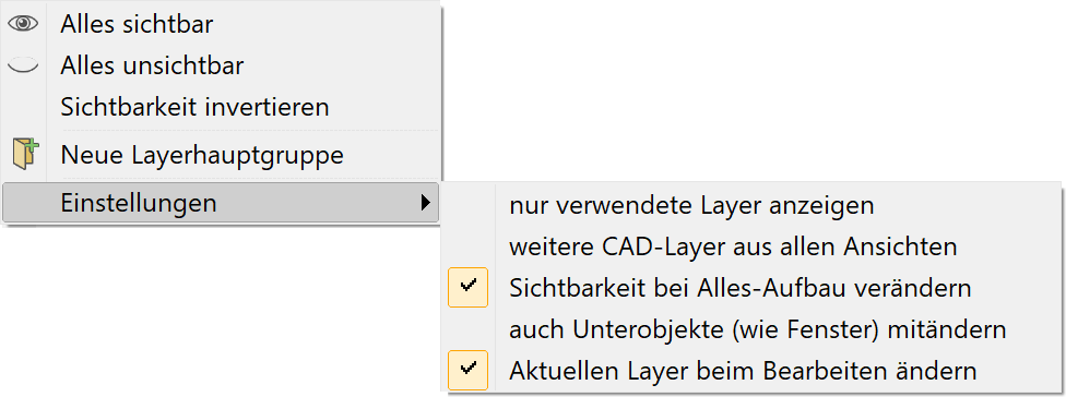
View all
Switches all layers to visible.
All invisible
Switches all layers to invisible.
Invert visibility
Switches all visible layers to invisible and all invisible layers to visible. The active layer is always visible.
New main layer group
Creates a main layer group at the end of the layer list.
Settings > Display used layers only
Layer manager is reduced to the layers used.
Settings > Further CAD layers from all views
This option is only required in views of the category view, section and detail. You have defined further layers under the heading "Further CAD layers" in a calculated view. You switch to a different view and require the same layers in this view. The layers are currently not displayed, however, as they do not contain any data. This function searches for defined layers in all created views.
Settings > Modify display with "Show all"
If this function is active, the visible layers are shown for the SHOW function.
Settings > Include sub objects (such as windows) in modify
The sub objects are included when this function is active. If a layer is modified for a wall, the sub objects windows, doors and wall openings are also modified.
Settings > Change current layer when editing
When editing objects (e.g. by clicking) the corresponding layer is displayed in the layer manager. If this setting is enabled the layer of the selected object remains the active layer. Otherwise, the previous layer is restored after the editing of the object is completed.
Layer name context menu
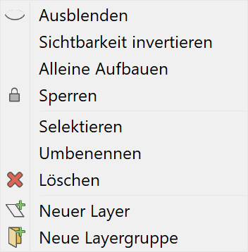
Hide/show
The HIDE or SHOW function appears depending on whether the layer is visible or invisible.
Show alone
Activates the layer and hides all other layers.
Lock
Select
All elements/construction parts that belong to the marked layer are marked in CAD. This selection can be used for a manipulation.
Rename
Modify a layer name.
Delete
Deletes the layer. If data has been allocated to the layer, the layer is stored under the heading "Further CAD layers". A layer under the heading "Further CAD layers" may not be deleted if data is still allocated to the layer.
New layer
Creates a new layer. The name can immediately be edited. The insert location depends on the Sorting. The layer is created directly beneath the selected layer for "user-defined" sorting.
New layer group
Creates a new layer group (such as Architecture), which can contain a number of layers.
Filter
A filter is an instrument used for switching a certain subset of layers to visible, invisible or visible alone.
Filter manager header functions

New filter
![]()
A query appears if an empty filter or a filter with all visible or invisible layers should be created.
Additional layers can be dragged into the filter using drag and drop.
Delete filter
The selected filter is deleted.
Filter manager context functions
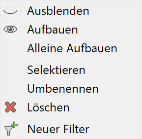
Hide
Hides all layers of the filter. If the active layer is included, it stays visible.
Show
Displays all layers of the filter.
Show alone
Only the layers of the filter are displayed. If the active layer is not contained in the filter, the first layer of the filter is activated.
Select
All elements/construction parts that belong to the layers in the filter are marked. This selection can be used for a manipulation.
Rename
Modify the filter name.
Delete
Deletes the filter. If the context menu is called up for a specific layer, the entire filter is not deleted but only the individual layer from the filter.
New filter
Creates a new filter.