Line types
Nine different standard line types and freely definable line types are available.

The freely definable line types are not available everywhere.
User-defined line types
|
|
Properties bar of 2D drawing elements |
| Settings menu > User-defined line types |

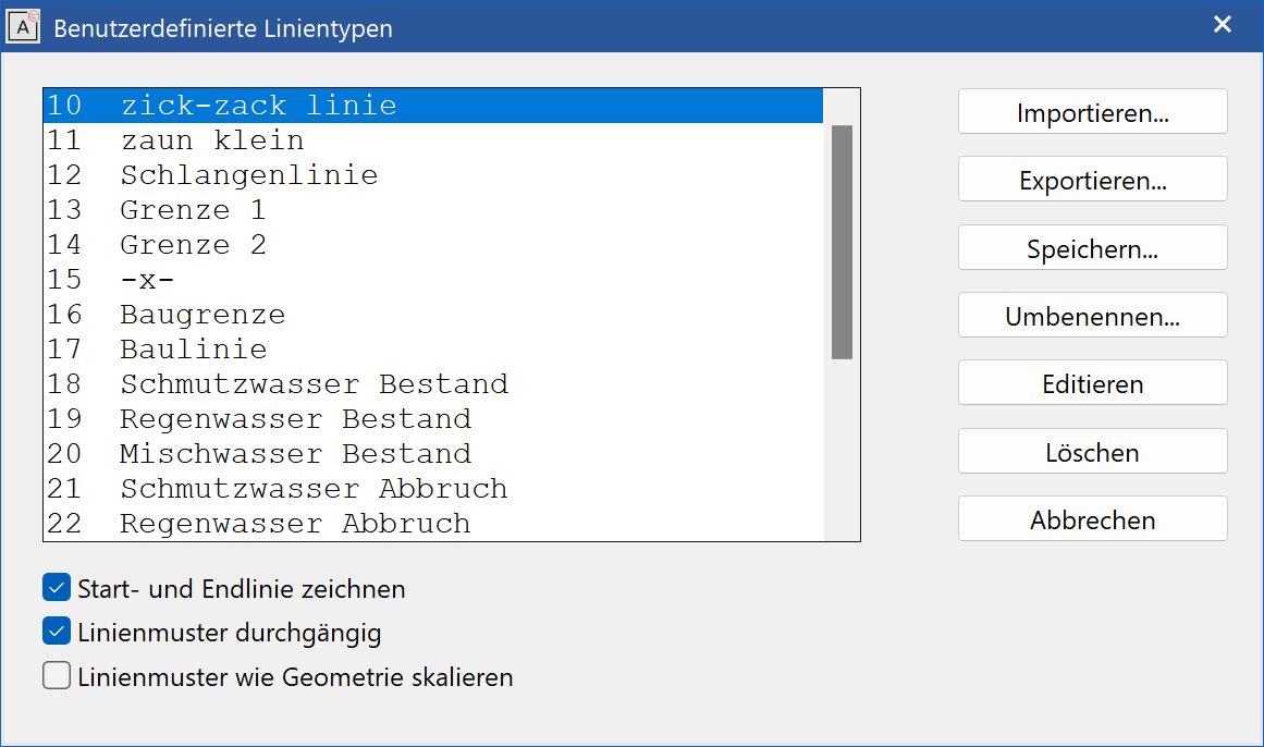
Management window for the user-defined line types
Import

Allows line types that were exported on a different workstation from ELITECAD to be imported.
Export

The selected line type can be exported as a file. The line type can be imported on a different workstation or in a remote office.
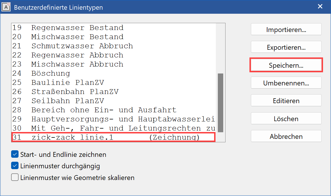
Save

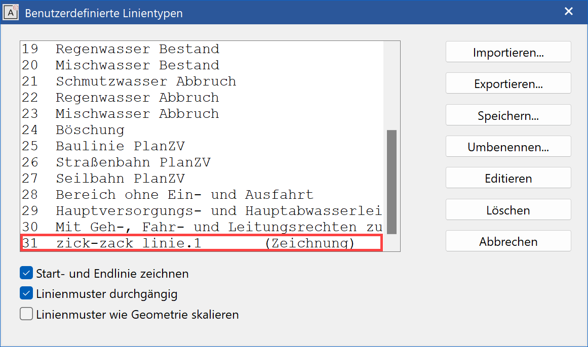
If a drawing is loaded that contains line types that are not available to you, these are labelled in the list as (drawing). This is also the case if you have edited a line type.
Line types must be saved in order for them to be permanently available.

If the name of a temporary or editable line type already exists, (.1) is added to the end of the name. If the line type is saved now, a message appears to inform the user that the line type name is not unique. Enter a new name, which may not start with a number.

Rename

The line type can be given a new name.
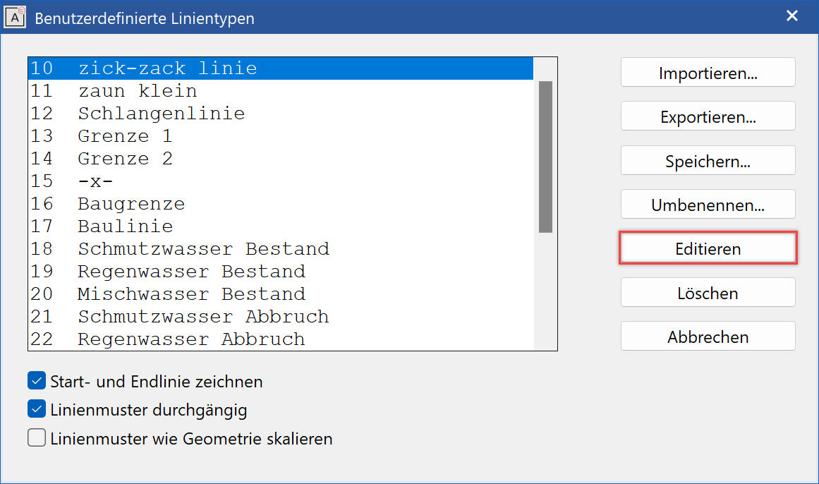
Edit


Allows new line types to be edited and created.
After calling up the function, the line type that is selected in the list is displayed in the graphics window.

The circles with the larger diameter specify the start and end of the line model.
The small dotted circles are only relevant if the option "DRAW START AND END LINE" is active. In this case, a line is automatically drawn between the large and small circle.
The white cross in the centre is the actual line model in this example.
If the editing process is complete, a query appears on the screen.

Overwrite original
The editable line type is overwritten. The line type must be saved in order for it to be permanently available.
Append to list end
The modified line type is added at the end of the list. The line type must be renamed and saved in order for it to be permanently available.

Reject modifications
The modifications made are not saved.
Delete

The marked line type is deleted. This is only possible in an empty drawing, however.
Cancel

Cancels editing or closes the dialog window.
Draw start and end line

If the option is set, an automatic line is drawn to connect the large and small circle of the line model.
Original example

| Without start and end line | With start and end line |
|---|---|
 |
 |
Line model contiguous

If this option is not selected, a direct connecting line is always drawn in the corners if there is no more space in the line model. If this option is selected, the line model is always completely visible even if the corners overlap.
| Line model not continuous | Line model continuous |
|---|---|
 |
 |
Scale line model as geometry

If this option is not selected, the size of the line model always stays the same in the printout, regardless of the scale set. If this option is selected, the line model is scaled using the scale of the drawing.
Workshop
Create new line type
Select the function DRAW LINE and then the line parameters in the property bar.
![]()
Select the line type (e.g. border 2) and click Edit.

The line model is displayed in the graphics window. Add to the drawing using the drawing functions.
| Template | New line model |
|---|---|
 |
 |
Click "Complete edit" and then on "Append to list end".


The new line type is displayed in the list. Click on Save.

Enter a new name and confirm it with  .
.

The new line type is available for use.
