Load and Save
File selection for loading and saving
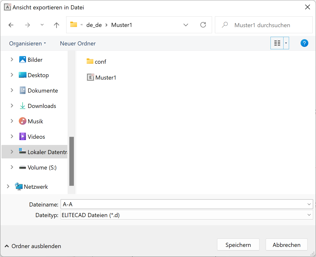
Loading and saving functions call up the Windows file selection. The dialog window may appear different depending on the operating system.
All files listed under "File type" can be loaded.
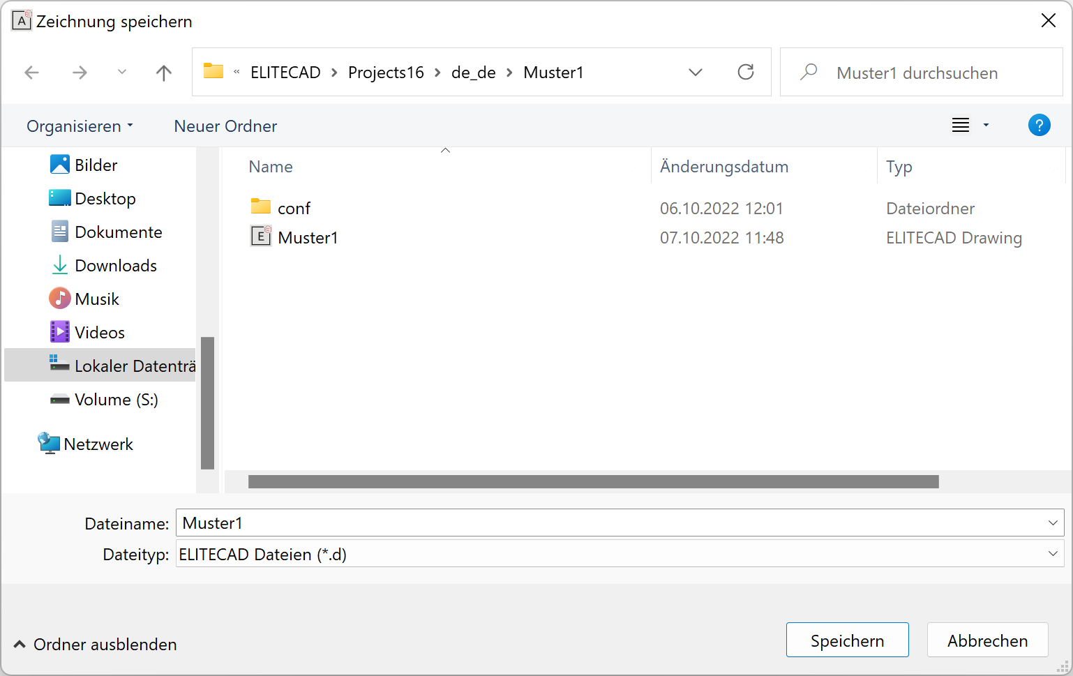
When selecting a project, the directory path for loading and saving it is set automatically to the project path. The most recently used path is opened for libraries, symbols and graphics.
![]() ELITECAD symbol
ELITECAD symbol
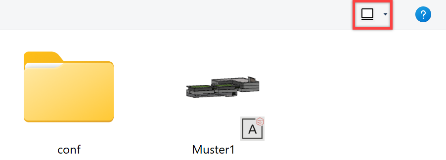
The display can be switched to "large symbols" to find out more about the contents of the ELITECAD file. A preview image of the file appears.
Using file type, users can filter whether only ELITECAD files or all files (necessary for loading CAD400 files) are displayed. If "ELITECAD files" is set for the file type, the file extension ".d" is automatically added to the file name when saving. If the file type is set to "All files", then you need to add this file extension to the file name. Files with the extension ".d" are displayed together with the ELITECAD symbol in Explorer.
Tip
All other common file formats can be selected directly under the file type. You therefore do not have to open all user interface dialog windows in order to load certain formats.
New
|
|
Toolbar *main functions |
| File menu > New | |
| Ctrl + N |
This function starts a new drawing with the title "unnamed.d".
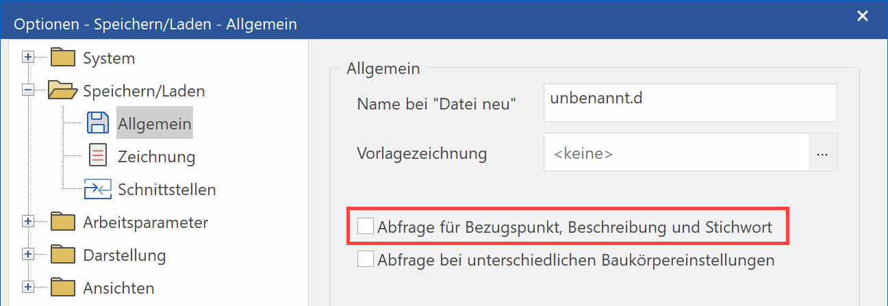
A number of pre-settings can be set in the OPTIONS.
Menu SETTINGS > OPTIONS > SAVE/LOAD > GENERAL
The name for "New file" can be specified in this directory and the user can decide at the same time whether a master drawing should be loaded.
OPTIONS > WORK PARAMETERS > NEW DRAWING
Various basic parameters can be set for the new drawing here.
Scale, unit, page format, angle unit, etc…
Having selected the function, if a drawing was loaded and modified, a query appears asking whether this drawing should be saved. A new drawing is then started.
If a file has already been loaded and has unsaved modifications, a confirmation prompt appears. (For details, see Exit.)
Load
|
|
Toolbar *main functions |
| File menu > Load… | |
| Ctrl + O |
If a file has already been loaded and has unsaved modifications, a confirmation prompt appears. (For details, see Exit.)
If the work area is empty, the dialog field "Load drawing" appears. The drawing required can now be selected and loaded.
Recently loaded files
|
|
File menu > Recently loaded files |
The eight most recently loaded files can be displayed with a corresponding path and be directly loaded.
Load work copy
|
|
Toolbar *main functions |
| File menu > Load work copy |
This function loads the most recent work copy.
If the function is called up via the menu FILE > LOAD WORK COPY, a dialog field "Load file" appears and old work copies can be loaded.
Show
|
|
File menu > Show… |
This can be helpful for copying data from existing plans into the current project via the clipboard.
In ELITECAD Architecture, the program is started for a second time.
In ELITECAD Mechanics the ELITECAD Viewer is started.
Insert graphic
|
|
Pixel toolbar |
| Menu Insert > Graphics… |
This function is used to load pixel graphics in TIFF, JPEG, BMP, PNG and GIF format.
The graphic can be manipulated accordingly using the functions from the Load/position property bar before being positioned.
The reference point can also be modified using the function MODIFY REFERENCE POINT.
Position
|
|
Insert toolbar |
| Insert menu > Position… |
This function loads an existing drawing into the current drawing. In ELITECAD Architecture, the drawing is assigned to the current structure and storey if it does not contain data from multiple storeys. The drawing is loaded into if this is the case.
The drawing is adjusted to the respective scale when being positioned.
The drawing can be manipulated accordingly using the functions from the Load/position property bar before being placed.
The reference point can also be modified using the function MODIFY REFERENCE POINT.
Load into
|
|
Insert toolbar |
| Insert menu > Load into… |
This function loads an existing drawing in ELITECAD Architecture into the current drawing with its specific storey and structure settings. The drawing is adjusted to the respective scale when being loaded.
The following query window for the position appears after activating this function.
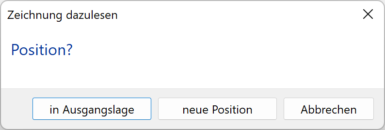
To start point
The drawing is placed exactly as saved.
New position
The drawing can be placed in any given position.
Insert OLE object
|
|
Insert toolbar |
| Menu Insert > OLE object… |
OLE stands for Object Linking and Embedding. This function allows users to add multiple data to an ELITECAD drawing from multiple other applications. For example, an image that was created in a graphics program can be integrated into ELITECAD. The special feature to note here is that this embedded image can be edited with the original graphics program directly in ELITECAD by double-clicking on it.
The OLE objects are either embedded in ELITECAD or linked with the original file.
The OLE functionality is provided by the operating system (Microsoft Windows). OLE does not support all functions and features of third-party programs. For example, only the first page is imported from a text document.
The dialog field "Insert object" appears after activating this function.
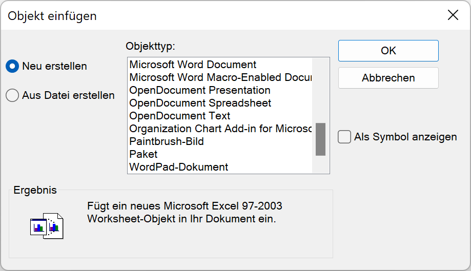
Create new
The corresponding application for generating a file can be selected under "Create new". Confirming with  always starts the program before the document, worksheet, etc. is positioned in the ELITECAD drawing.
The data has to be saved in the external programs menu before refreshing it in ELITECAD.
Files created in this way are always embedded in ELITECAD.
Create from file
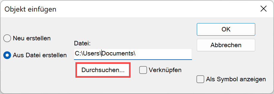
An existing document can be selected and inserted into ELITECAD using this option. If the button "Link" is not active, the document is embedded in ELITECAD. Otherwise it is linked.
If the button "As Symbol" is activated, the file itself is not displayed but only a symbol.
Explanation
OLE objects can either be linked or embedded. Users can find out whether an object is linked with ELITECAD or not with the menu item EDIT > LINKS or in the menu of the open application (use refresh and not save).
Link
A linked object is a reference to data in another document. You can use the same data in multiple drawings. If the original document is modified on this basis, the links in ELITECAD are, depending on their properties, refreshed automatically as soon as the corresponding drawing is loaded. All links can be refreshed via the menu item EDIT > REFRESH LINKS for loaded drawings. The properties of the links can be modified with the menu item EDIT > LINKS.
Please note that the object can also be edited in ELITECAD by double-clicking on it and that the original document can therefore be modified.
Embed
If an object is embedded, the data from this document is integrated into ELITECAD as a copy and no longer connected to the original document.
Tip
Parts of documents can be inserted into an ELITECAD drawing with the Windows clipboard. Select the parts to be copied in the corresponding application and move them to the clipboard. These parts can be incorporated into the ELITECAD drawing. These objects are embedded in ELITECAD and can be opened with their original application and edited by double-clicking on them.
Edit links
|
|
Edit toolbar |
| Edit menu > Links… |
The properties of linked OLE objects can be modified with this menu item.
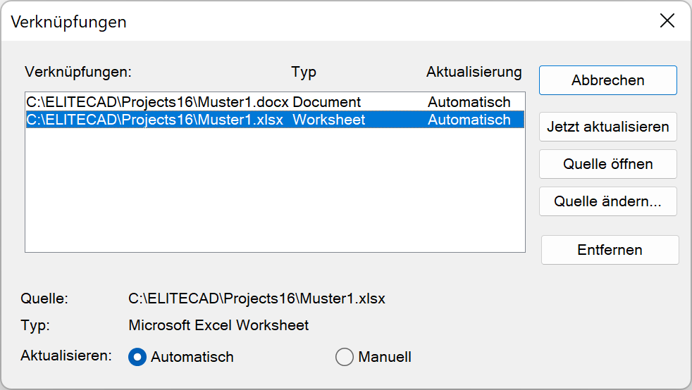
All links that are contained in the drawing are always displayed.
Update now
The selected link is refreshed.
Open source
The selected link is opened with the corresponding application.
Change source
A different document can be added to the background of the selected link.
Remove
The selected link is deleted. While the graphic remains in ELITECAD, it can no longer be edited.
Refresh:
If a link is set to "automatic" (default), it will always be refreshed when loaded.
If a link is set to "manual", however, it must be refreshed either via the function UPDATE NOW or via the menu item EDIT > REFRESH LINKS.
Refresh links
|
|
Edit toolbar |
| Edit menu > Refresh links |
All links in the loaded drawing are refreshed.
Save
|
|
File toolbar |
| File menu > Save | |
| Ctrl + S |
The drawing is saved under its current name and file type, which can be seen in the title line.
Tip
The complete drawing is always saved, regardless of whether "elements", "geometry", "text", "arrows", "dimension" and "hatch" are visible.
Save as
|
|
File toolbar |
| File menu > Save as… | |
| F12 |
This function saves the current screen contents of the existing drawing in a new file. A new file path and file name can be selected in the Windows file selection. If a pre-existing name is selected, a confirmation prompt appears.
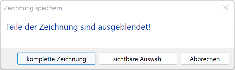
Explanation
If not all of the data of the design model is assembled, a query appears asking the user whether the complete drawing or only the visible part of the drawing is to be saved. Parts from the design model can be saved individually as a template in this way.
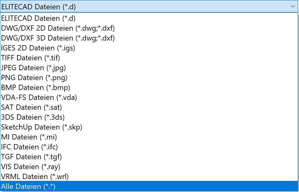
The following file formats can be written instead of an ELITECAD file: - DXF/DWG 2D files (.dxf,.dwg) - DXF/DWG 3D files (.dxf,.dwg) - IGES 2D files (.igs) - TIFF files (.tif) - JPEG files (.jpg) - BMP files (.bmp) - VDAFS files (.vda) - SAT files (.sat) - 3DS files (.3ds) - MI files (.mi) - IFC files (.ifc) (only in ELITECAD Architecture) - TGF files (.tgf) - VIS files (.ray) - VRML files (.wrl) Data loss occurs if an entire design model is saved in one of these formats as only corresponding areas are saved depending on the format.
Option for Save as
Additional queries can be activated in the OPTIONS. (Standard is switched off)
Attention: These queries must then be confirmed otherwise the drawing will not be saved.
Either the reference point for a saved drawing can be assigned with one of the common capture modes or the current origin (centre of page) is used as a reference point by pressing the Enter key. This will be the current reference point later on when the drawing is loaded with the functions POSITION, LIBRARY and SYMBOL.
The query Enter description appears. If the "Graphics preview" is called up for one of the loading functions, this entry is displayed as a tip (quick info) when you hold the mouse over the preview image.
The keyword is an additional piece of information for the drawing.
Save work copy
|
|
File toolbar |
| File menu > Save work copy | |
| Ctrl + W |
The work copy is a temporary backup of the drawing. A distinction is made between an automatic and a manual work copy.
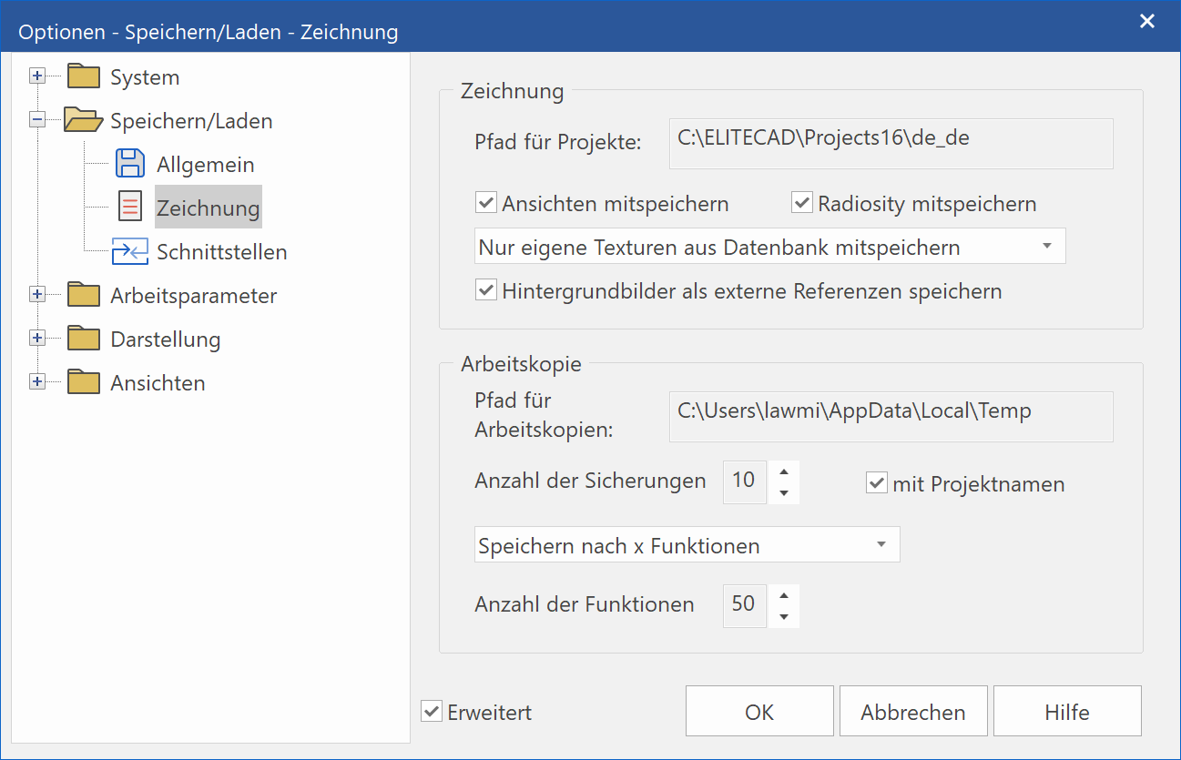
The function saves a manual work copy. The file is saved in the directory of work copies (ELITECAD configuration). A certain number of work copies can be accessed (SETTINGS > OPTIONS > SAVE/LOAD > DRAWING). A suffix (".0", ".1", ".2", …) is appended to the work copies. The work copy with the suffix ".0" is the most recent.
Work copies can also be saved as project-specific in ELITECAD Architecture (SETTINGS > OPTIONS > SAVE/LOAD > DRAWING). The name is generated as follows: \
Note
This function ignores all visibility filters and saves the entire drawing in the backup file.
Automatic work copy
An automatic work copy schedule can be activated in the OPTIONS (SETTINGS > OPTIONS > SAVE/LOAD > DRAWING). The work copy is given the extension "_auto" in its name. In the OPTIONS, you can set the number of work steps to be carried out before a work copy is saved. The manual work copies are not affected.
Save for transfer
|
|
File menu > Save for transfer… |
This function can be used for forwarding files, e.g. to a third-party office, without having to worry about references.
All relevant data is saved into a single file independently of the current settings. (e.g. OLE objects, background images, visualisation materials, views, references)
Export view
|
|
File toolbar |
| File menu > Export > View... |
In order to load all views, sections, details and plot views generated in ELITECAD individually or to decouple them from the design model, they must be saved as separate drawings with the function EXPORT. When doing this, they lose all object intelligence of the construction parts.
Send
|
|
File toolbar |
| File menu > Send |
New · 16 R1 · Improvements
This opens your email and attaches the current model to it. This sends the complete file including hidden objects and views.
Create archive
|
|
Menu File > Create archive |
This function can be used for forwarding files, e.g. to a third-party office, without having to worry about references.
All relevant references such as OLE objects, background images, visualisation materials, etc. are exported into a blank directory.
Load archive
|
|
File menu > Load archive |
A previously generated archive is loaded with all references, such as OLE objects, background images, visualisation materials, etc.
Insert reference plan
|
|
Reference plan toolbar |
| Insert menu > Reference plan > Load into… |
This function inserts an ELITECAD drawing as a reference plan. The reference point of the drawing is transferred. The reference plan is assigned to the original storey. The reference plan is displayed in a pen colour and can neither be edited nor activated. The capture points can be selected, however. The settings in SETTINGS > OPTIONS > REFERENCE PLAN apply for the display (pen type) and the procedure for saving and printing.
Position reference plan
|
|
Reference plan toolbar |
| Insert menu > Reference plan > Position… |
This function inserts an ELITECAD drawing as a reference plan. The position of the reference plan can be redefined. The reference plan is assigned to the active storey. The reference plan is displayed in a pen colour and can neither be edited nor activated. The capture points can be selected, however. The settings in SETTINGS > OPTIONS > REFERENCE PLAN apply for the display (pen type) and the procedure for saving and printing.
Delete reference plan
|
|
Reference plan toolbar |
| Insert menu > Reference plan > Delete |
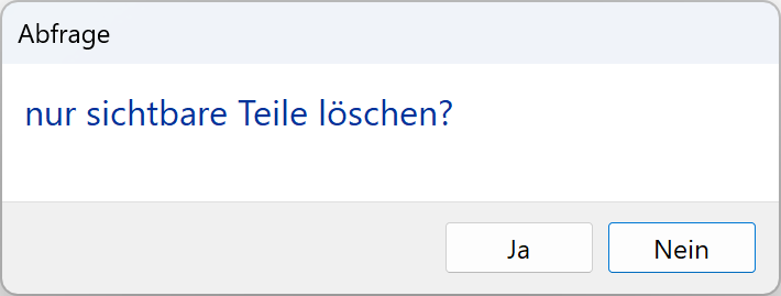
This function deletes a reference plan. If multiple reference plans are loaded, all are deleted. If reference plans have been hidden, however, a query appears asking you whether you want to delete only the visible reference plans or all reference plans.
Hide reference plan
The reference plans can be hidden in the screen settings Ctrl + Q .