Materials Editor Options
Base colour
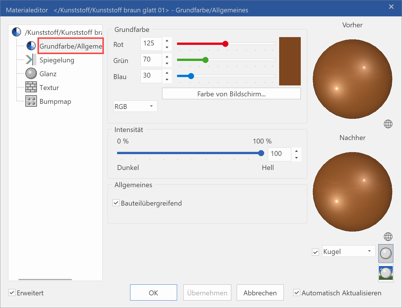
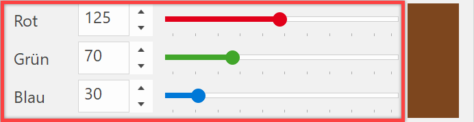
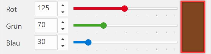
There are multiple selection options for the base colour. The colour selected is always displayed with the RGB values.
RGB

The values can be entered directly into the entry fields or set with the slider.
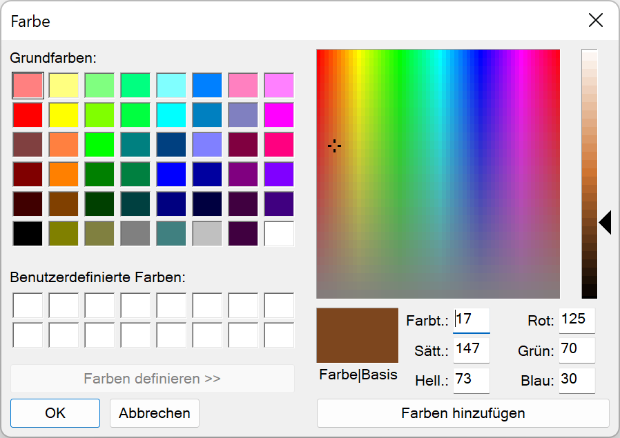
The standard Windows colour dialog box appears when clicking on the colour button.
Colour from screen

The cursor switches to a pipette symbol by clicking on this button. You can now click on any surface in the graphics window or in the preview window. This colour value is then set.
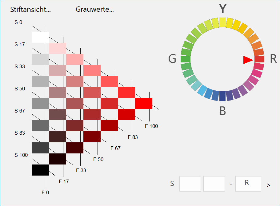
M-NCS

Switch to the M-NCS view by clicking the right-hand selection button.
M-RAL
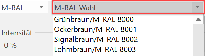
You can select an M-RAL colour by clicking the right-hand selection button.
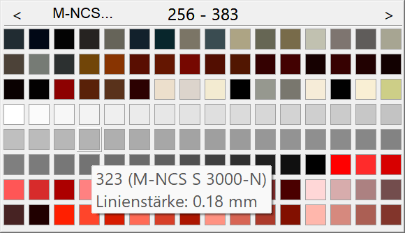
Pen
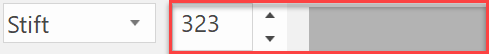
The pen number can be entered directly into the entry field and you can proceed to the Pen selection menu by clicking the selection button.
Intensity
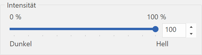
You can change the brightness of the base colour with this slider.
Across objects
This option is only used in ELITECAD Architecture. If the option is selected, the rendering of materials that are the same overlap for surfaces that meet. For performance reasons, this option may only be selected for materials that have a continuous pattern (exposed masonry, timber formwork).
This button only works if "Textures across construction parts" is active in OPTIONS (menu SETTINGS > OPTIONS > WORK PARAMETERS > ARCHITECTURE).
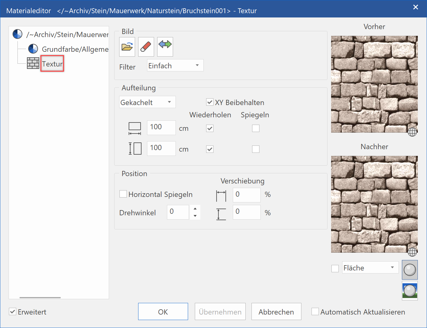
Texture
The texture effect offers you extensive options for modifying the characteristics of image files or for making modifications yourself.
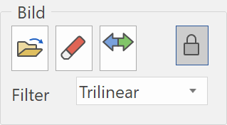
Image
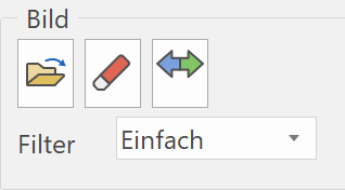
Select image
![]()
Opens the standard Windows dialog with which you can select an image file as a texture image.
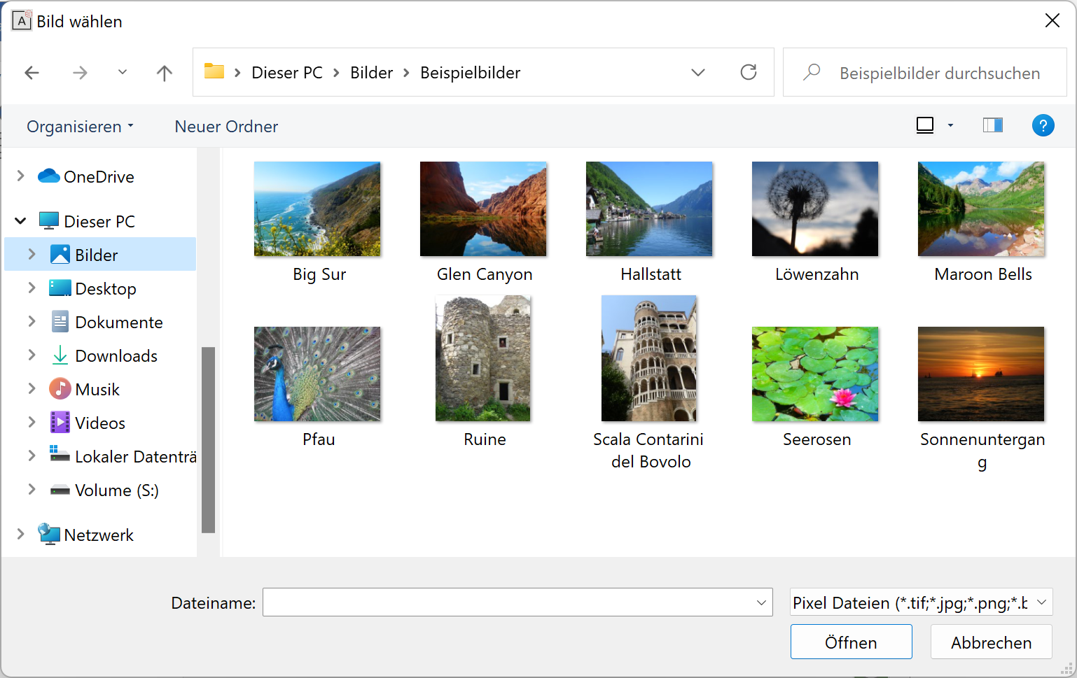
The following file types can be selected: .tif, .jpg, .bmp, .gif, *.png
Explanation
Each texture that is loaded by the program when rendering uses internal memory. Users should note that the textures should not be overly large in terms of their data volume. It should be judged depending on whether they want to view the design model from a distance or close up.
Delete image
![]()
Deletes a previously selected image. A confirmation prompt appears to ensure you really want to delete the image.
Edit image
![]()
Opens the textures manager.
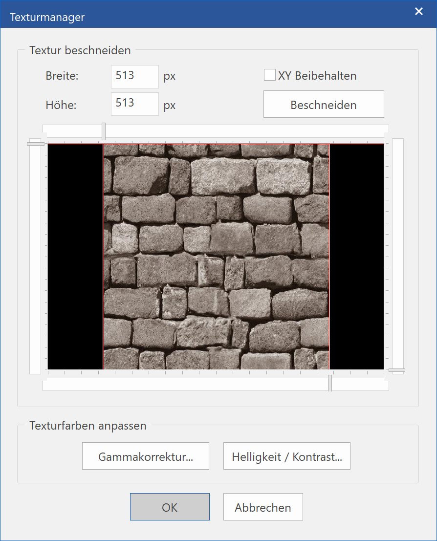
There are different options for changing the texture image in terms of its size or colour.
Trim texture
You can reposition the texture on the margins of the preview image or on the trim lines themselves. If you then perform the function TRIM, the image is reduced in size and the image cut-out enlarged. You can repeat this until the procedure is confirmed with  or cancelled with
  .
.

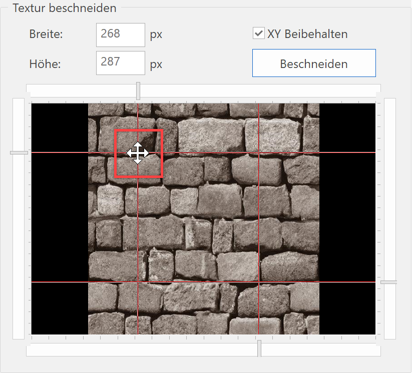
The new dimensions (pixels) are revised on a continuous basis and can be entered into the entry field manually.
![]()
If the option MAINTAIN XY is activated, the trim lines are fixed in their positions and can be moved all together.
Gamma correction
A gamma correction is a change to the colour balance between the separate base colours red, green and blue.
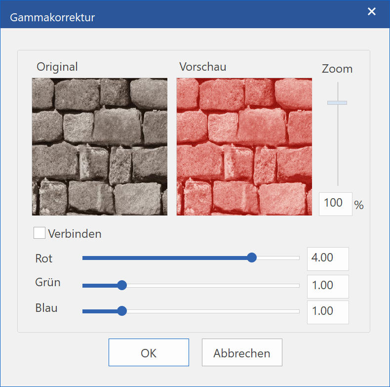
The values can be entered directly into the entry fields or set with the slider. If the option CONNECT is activated, the three sliders are connected.
You can zoom in on the preview image either with the mouse wheel or with the slide on the right-hand side. The image section can also be moved by left-clicking it.
Brightness/contrast
Modifying the brightness and contrast of an image has an impact on highlighting, shadows and mid-range colours. This function is normally used to correct images that are too bright or too dark.
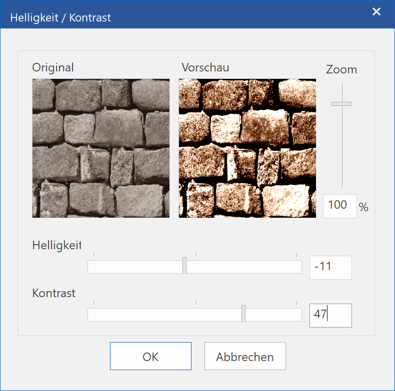
The values can be entered directly into the entry fields or set with the slider.
You can zoom in on the preview image either with the mouse wheel or with the slide on the right-hand side. The image section can also be moved by left-clicking it.
Texture filter
Textures that display brightness fluctuations close to each other and are very small can appear with the so-called moiré effect from a certain distance. This is often the case for exposed masonry or flagging.
If, for example, the joints are smaller than a pixel on the monitor, the graphic/video card and the monitor decide randomly whether a bright or dark pixel is used. To avoid this effect, the texture filter can be set to "Simple", which performs a special kind of smoothing on the texture and corrects the moiré effect. If this effect is still visible despite the simple filter, it can be set to "Tri-linear".
Note that these options increase the memory requirements and the rendering time. Therefore, only use it when necessary.
| Without texture filter | with texture filter |
|---|---|
 |
 |
Tip
Texture filters are only applied for image rendering if the option TEXTURE FILTER IS SELECTED in the render parameters.
Division
There are various settings options for displaying materials realistically in the geometry in terms of size and scaling.
Tiled
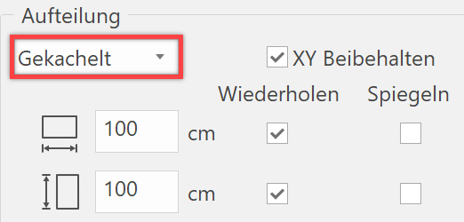
The real size of the texture image can be entered here. The entry always refers to the entire texture image. If you no longer know what the original image looks like, you can display it as a Texture preview here.
If the option MAINTAIN XY is set, the fields for width and height are linked.
If the box "Repeat" is activated, the texture image is laid over the surface multiple times.
Users can specify under "Mirroring" whether a material mirrors or not when covering a surface.
Explanation
Unlike the process for rendering a solid image, which uses the graphics card, the rendering is performed via the ELITECAD software. As the hardware does not feature all functions for rendering the texture image in all variations, there may be optical differences between the two rendering types.
To ensure that the material appears in its final version, the image should be rendered from time to time. Alternatively, Area rendering can be used to avoid having to render the entire image.
Number
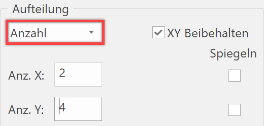
The number of repeats can be entered here. The material is displayed on the surfaces using these inputs.
If the option MAINTAIN XY is set, the fields for the number X+Y are connected.
Under "Mirroring", users can specify whether a material is alternately mirrored when allocating.
Stretched
The material is always projected onto the entire surface with this option, regardless of how large the surface is.
Position
Settings can be made here to specify the position of the texture on the geometry.
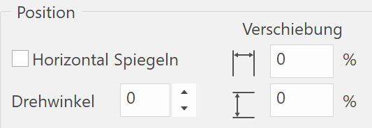
If the option MIRROR HORIZONTAL is selected, the original image is folded on the horizontal axis.
| Original image | Horizontal Mirroring |
|---|---|
 |
 |
The texture image can be rotated between 0° and 360° using the function ROTATE ANGLE.
For example, a formwork with a horizontal orientation can be displayed diagonally.
| Rotation angle 0° | Rotation angle 45° |
|---|---|
 |
 |
The texture can be shifted to a surface using the "Shift" entry fields.
| Without shift | With shift |
|---|---|
 |
 |
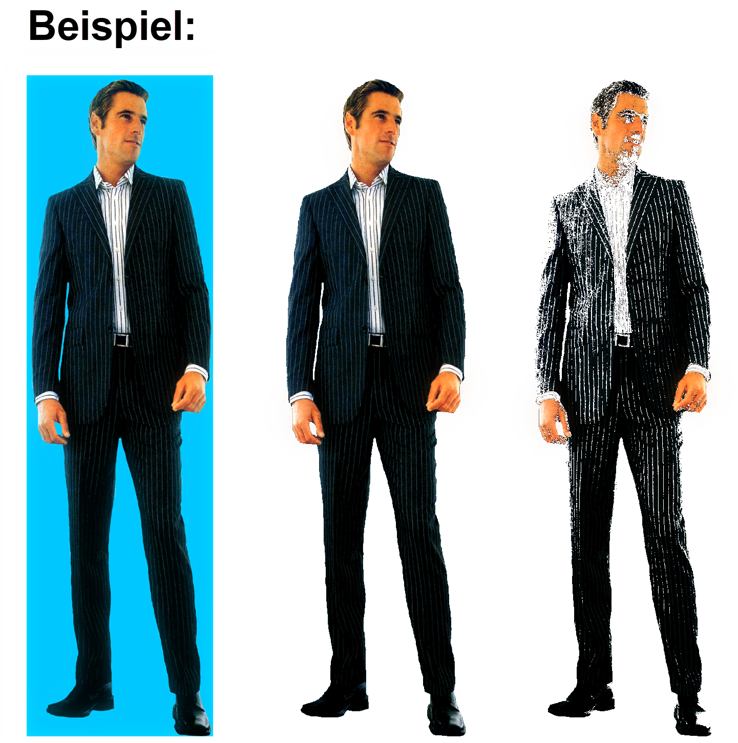
Blue screen
It is possible to switch a specific colour or a texture to transparent via the blue screen procedure. This function is especially suitable for displaying people, animals, plants and objects, etc. without displaying their background. This material must have a single-colour background or an alpha channel that is then transparently rendered to make a person or background visible, for example.
This effect is only available if a texture is available.
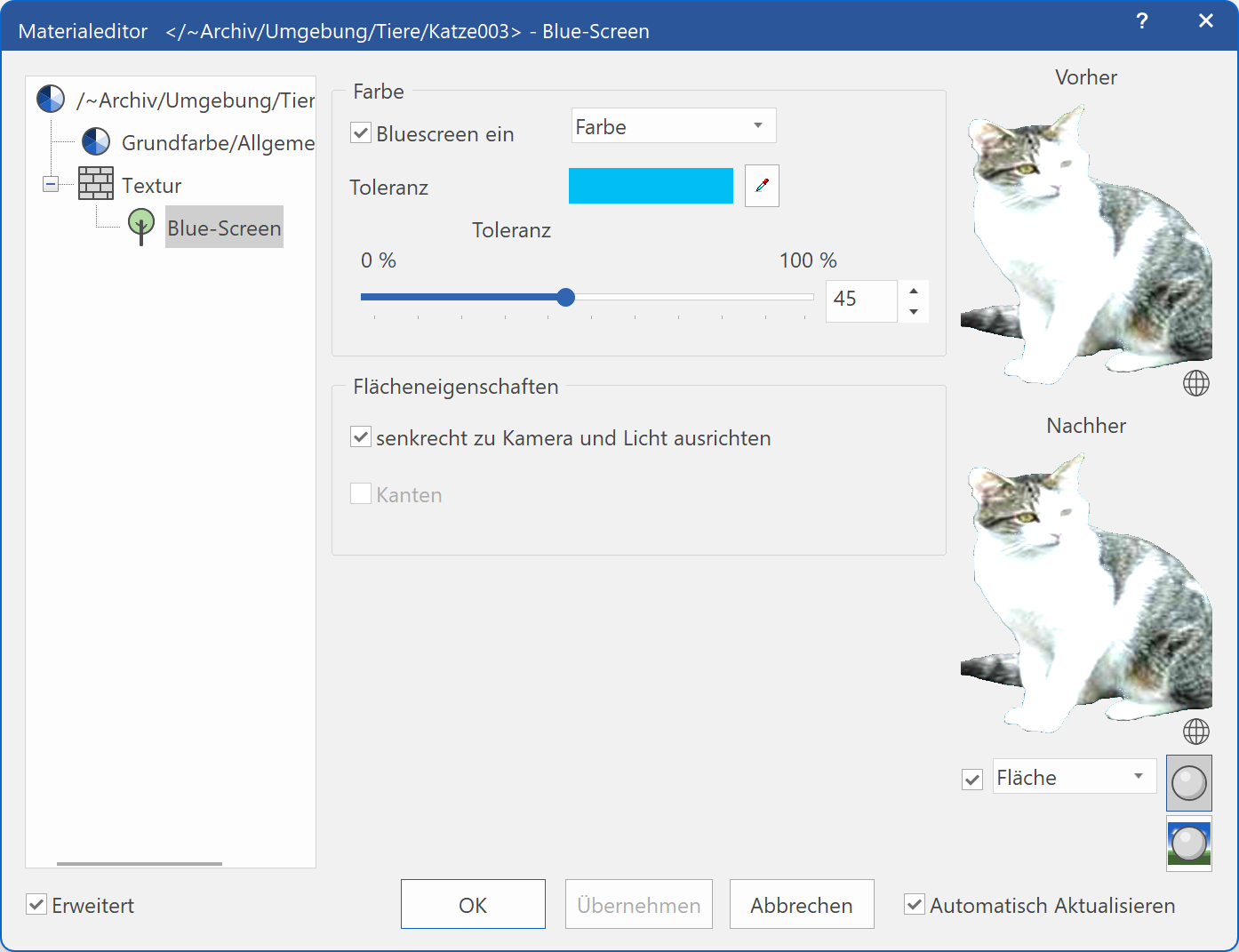
Colour
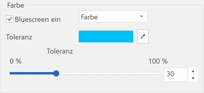
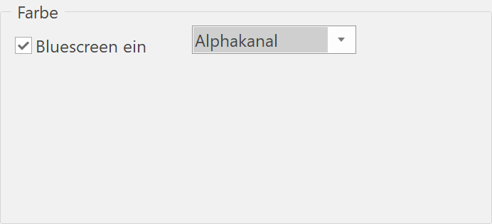
The type of transparency can be set if the option BLUESCREEN is selected.
The transparency values are applied directly from the texture bitmap for the setting "Alpha channel".
A colour can be selected for the COLOUR setting that is to be rendered transparently.
The standard Windows colour dialog opens via "Colour selection button". In this case, it makes more sense to use the pipette.
You can click on any surface in the work area or in the preview window and this colour value is then set.
Use the "Tolerance" slider to control the accepted difference of a colour to the transparency colour.
The material can then be allocated to a surface. It is best to use a freestanding surface that corresponds with the surfaces of the texture in its dimensions.
You can set the texture to cover an entire surface automatically by selecting the division "stretched" in the texture settings.
Tip
If your texture is not already displayed in front of a neutral background, you can use various image-processing programs for changing the colour.
Tip
If your texture is not already displayed in front of a neutral background, you can use various image-processing programs for changing the colour.
Bump map
As textures are based on two-dimensional images, they always appear "flat" when being rendered, i.e. with no illusion of depth. This kind of effect can be achieved with the bump map effect.
The depth structure is generated from bright and dark areas of the texture image.
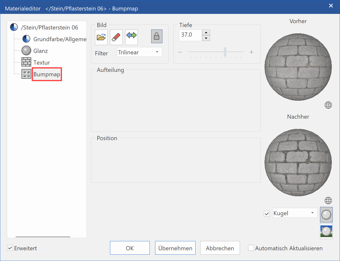
Image
The depth structure is generated from bright and dark areas of the texture image Texture.
Link with texture
![]()
![]()
You can use this option to define whether the image that you have selected under Texture is also to be used as a template for the bump map.
This means that if the little lock is locked (red), the image and the settings are the same for the texture and the bump map.
Tip
This option can be accessed if a texture image is already present. If the settings such as size and moving are modified for the texture, this also occurs automatically for the bump map.
If the little lock is unlocked (green), the image file that was loaded for this is used for the bump map.
Tip
This can also be used to create an illusion of depth for a material that does not have its own texture image.
Depth
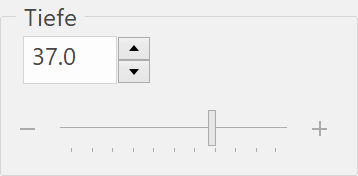
The bright and dark areas are displayed with different depths depending on whether a negative or positive value is entered. For example, bright areas face outwards and dark areas inwards.
Example with texture image and bump map
| Without depth | with positive depth |
|---|---|
 |
 |
Example without texture image and bump map
| Without depth | with negative depth |
|---|---|
 |
 |
The other settings such as segmentation and position are described under Texture.
Tip
The darker the texture image, the less visible the illusion of depth. This can be compensated with an additional shine effect.
Tip
The bump map is only applied for image rendering if the option BUMP MAPPING is selected in the render parameters.
Transparency
The transparency properties for a material can be specified here.
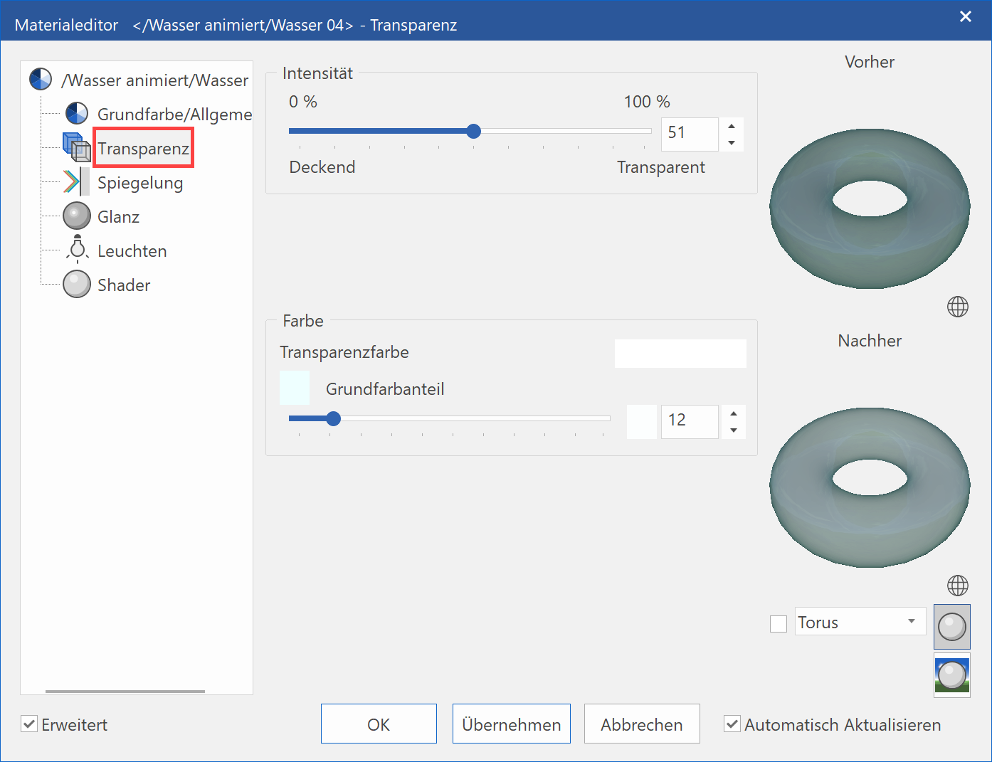
Intensity
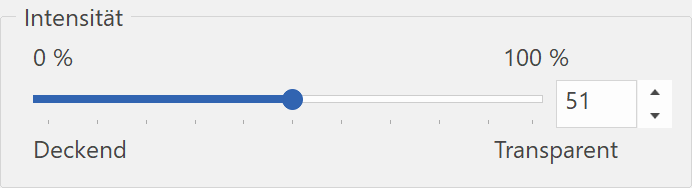
Use this slider to define the intensity of the transparency.
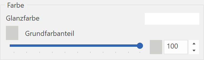
Colour
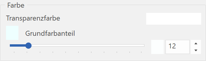
A special "transparency colour" can be selected that can be different from the base colour. The standard Windows colour dialog opens.
The function BASE COLOUR PART controls the share of the base colour part for the transparency. If the slide is set to 0, the "transparency colour" is applied. If the slider is set to 100, only the base colour is used.
Tip
The option COLOUR is only visible if the "Extended" check box is activated.
Refraction
If a light beam hits a boundary surface of two materials with a different refraction index, e.g. air and water, it is "bent", which means it changes its direction. The light is "refracted" at the border surface of the two materials.
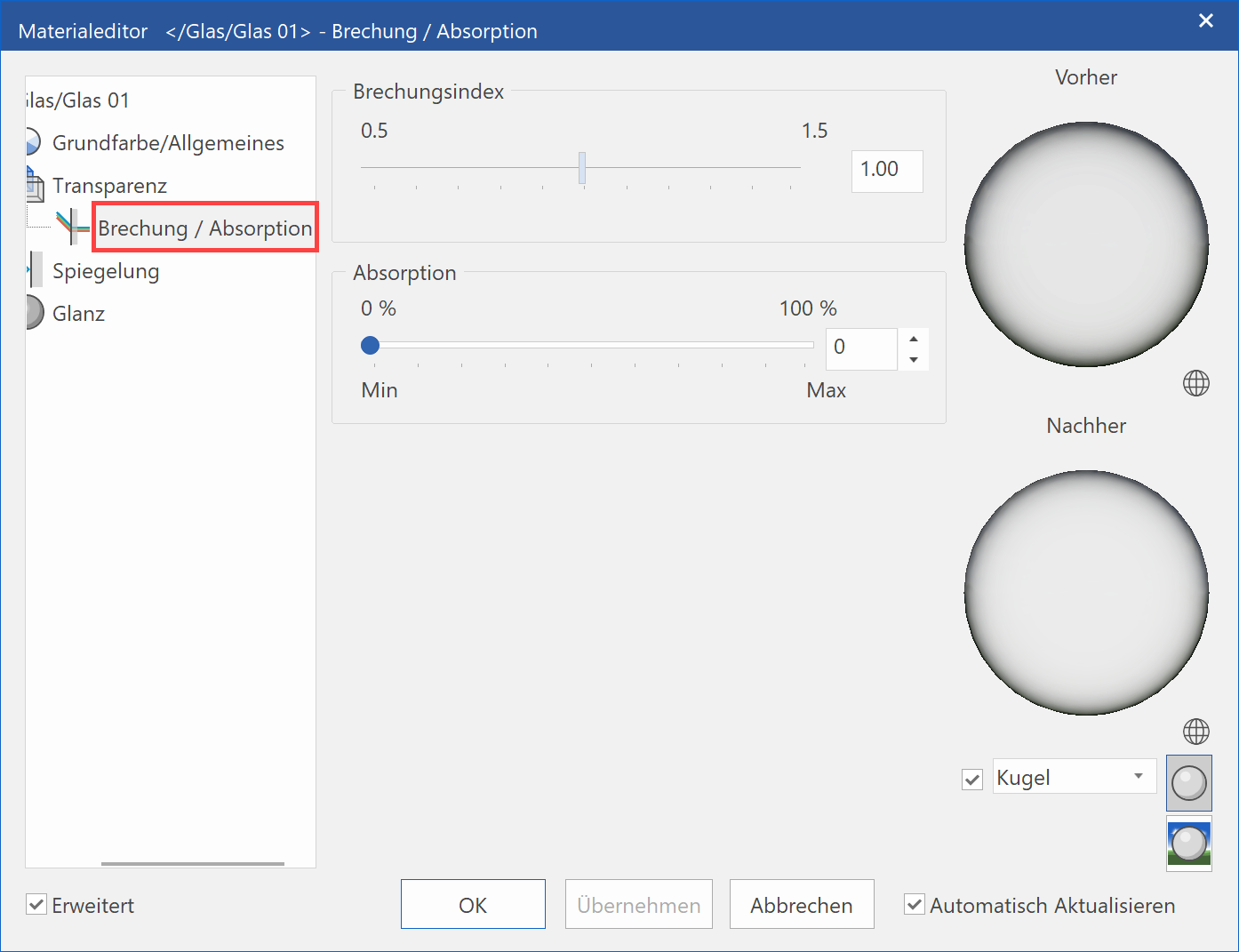
Refraction index
The refraction index can be changed from 0.5 to 1.5 with the slider. The value 1 is neutral.
| Example with value 1 | Example with value 1.33 for water |
|---|---|
 |
 |
Tip
The refraction is only applied for image rendering if the option MIRRORING, REFRACTION is selected in the render parameters.
Absorption
No light is absorbed behind the transparent surface for the value 0. It is dark behind the surface for the value 100.
Tip
The option ABSORPTION is only visible if the "Extended" check box is activated. Does not apply for windows and glass elements.
Mirroring
The mirroring properties for a material can be specified here.
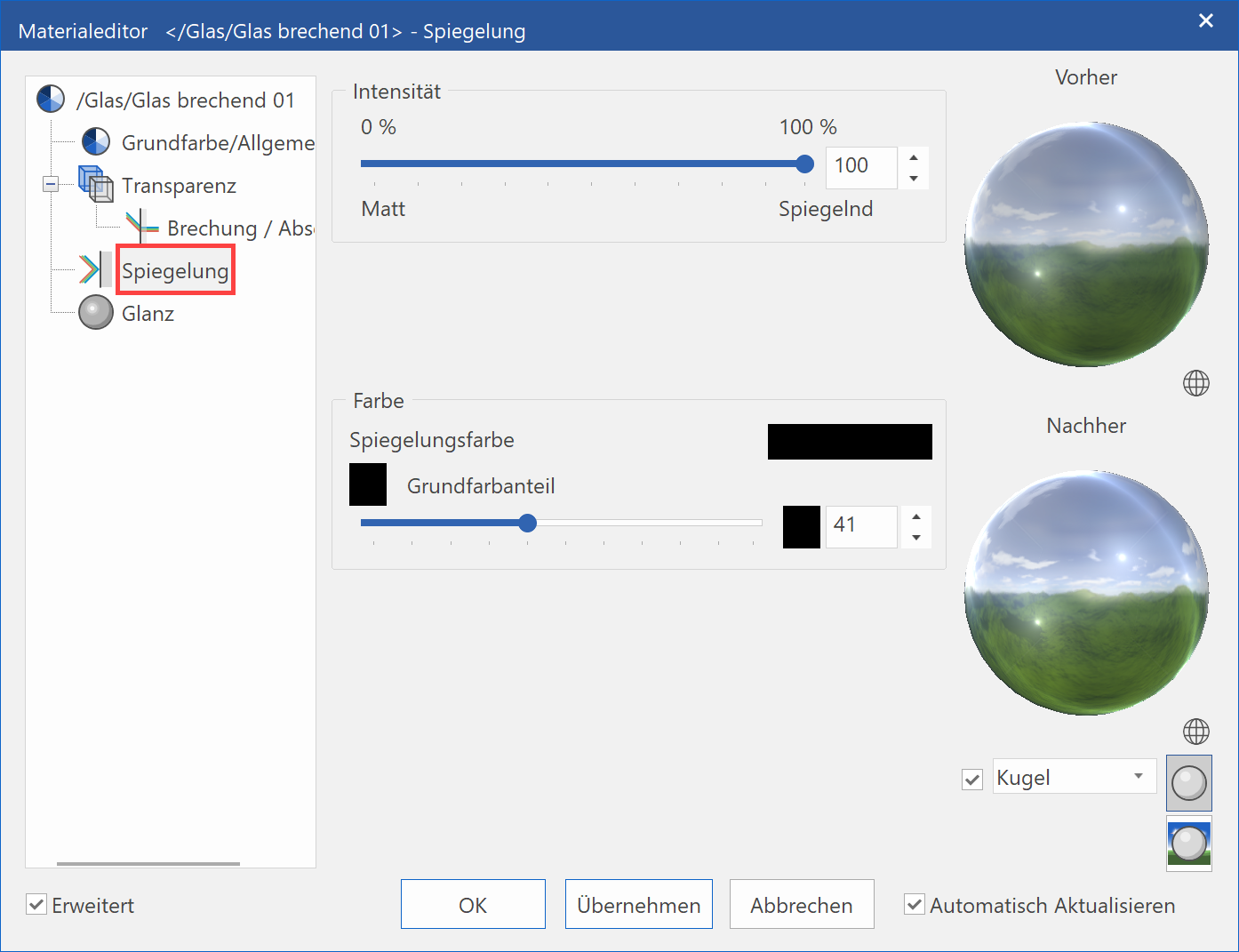
Intensity
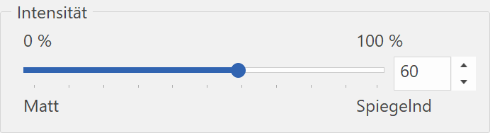
Use this slider to define the intensity of the mirroring.
Colour
A special "mirroring colour" can be selected that can be different from the base colour. The standard Windows colour dialog opens.
The function BASE COLOUR PART controls the share of the base colour part for the mirroring. If the slider is set to 0, only the "mirroring colour" is applied. If the slider is set to 100, only the base colour is used.
Tip
The option COLOUR is only visible if the "Extended" check box is activated.
Tip
The mirroring is only applied for image rendering if the option MIRRORING, REFRACTION is selected in the render parameters.
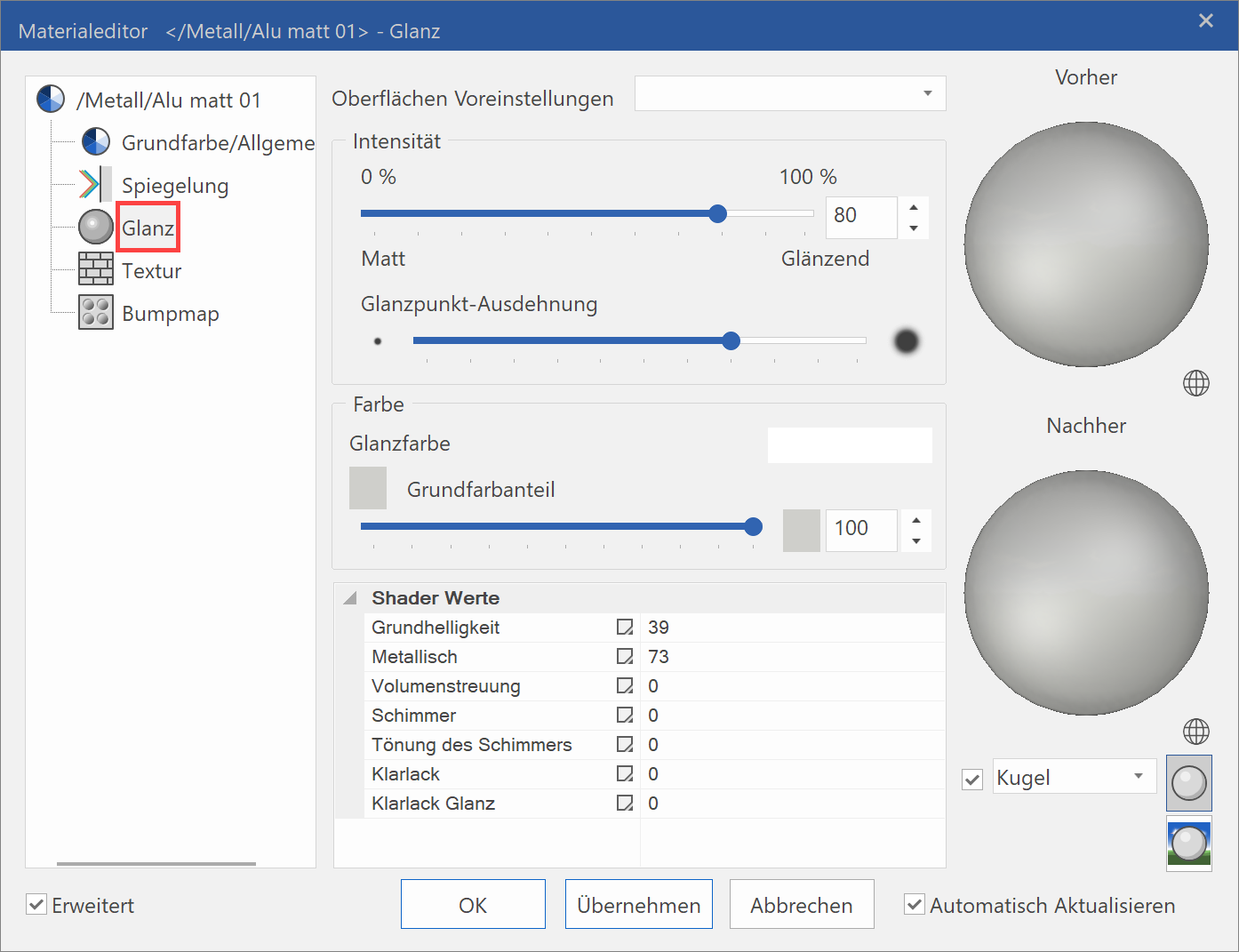
Shine
The shine properties for a material can be specified here.
Surface presets

Predefined shine settings for various material types simplify the configuration of shine.
Intensity
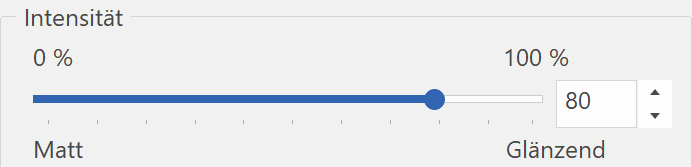
Use this slider to define the intensity of the shine.
Tip
The intensity can be overridden by up to a value of 600. Enter the corresponding value into the entry field.
Brightness extent
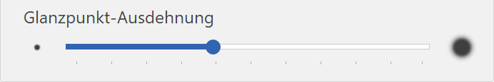
You can specify the width of the shine points with this slider.
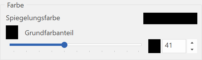
Colour
A special "brightness colour" can be selected that can be different from the base colour. The standard Windows colour dialog opens.
The function BASE COLOUR PART controls the share of the base colour part for the shine. If the slider is set to 0, only the "brightness colour" is applied. If the slider is set to 100, only the base colour is used.
Tip
The option COLOUR is only visible if the "Extended" check box is activated.
Shader values
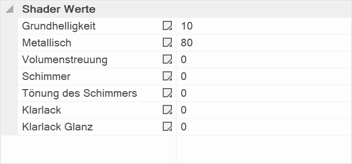
Visualisation of shine is also possible in real-time visualisation mode. It is necessary to activate shader technology first (see chapter: SETTINGS > IMAGE PROPERTIES). Select individual values and modify the values using the slider. Modifications are displayed immediately if the preview is enabled.
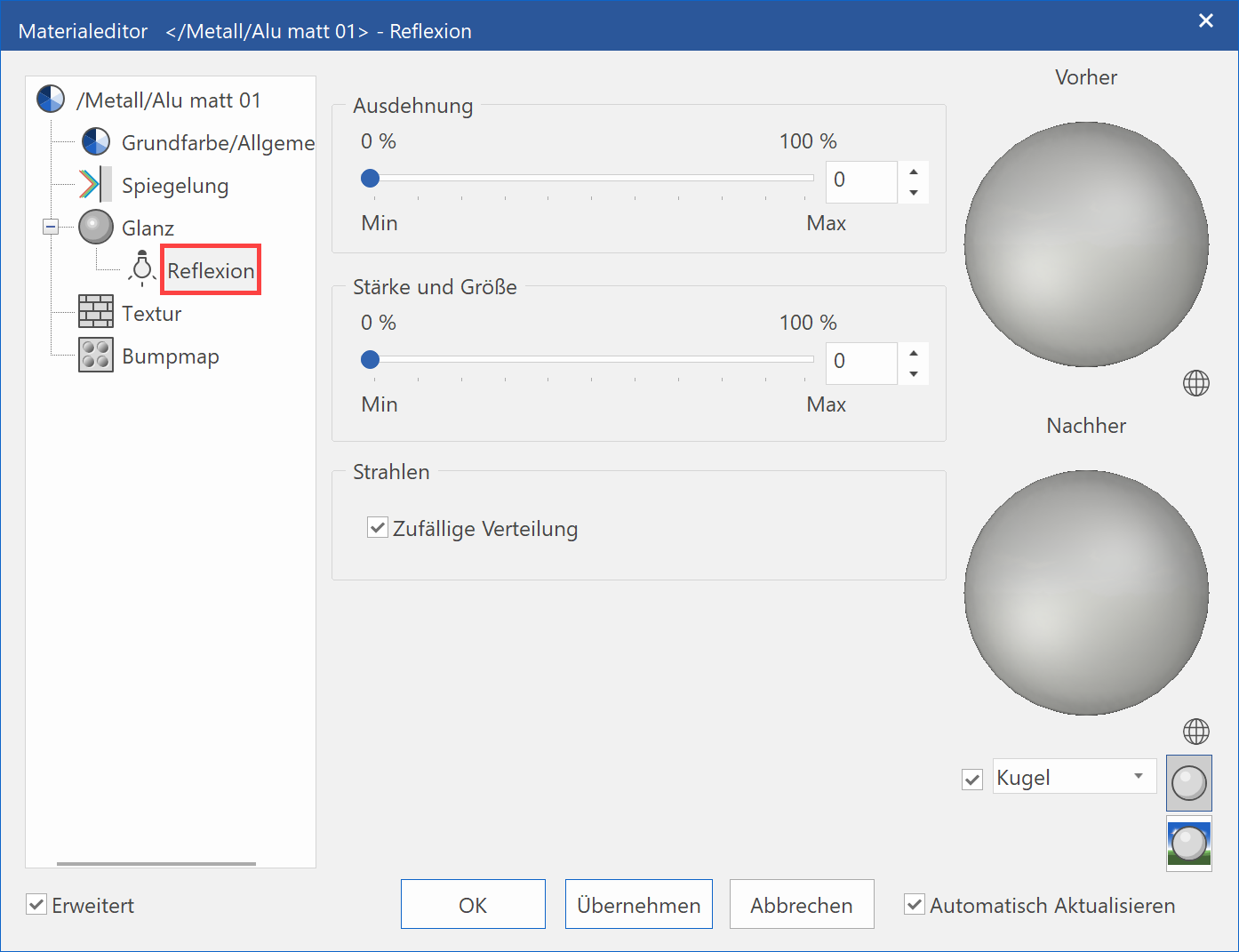
Reflection
The reflection properties for a material can be specified here.
This effect is only available if a shine is available. The appearance of the reflection points depends on the shine and light settings.
Extent
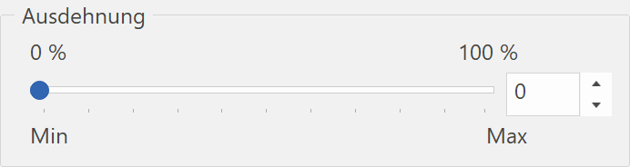
The higher the value you specify, the more likely it is that shine points will be generated.
| Extent 0% | Extent increased |
|---|---|
 |
 |
Intensity and size
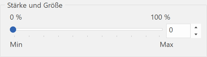
The higher the value you specify, the more intense the shine points generated.
| Low intensity | Intensity increased |
|---|---|
 |
 |
Rays
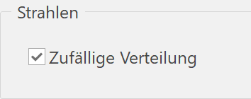
The rays are arranged in random order if this option is selected.
Illumination
You can specify the illumination of a specific material here.
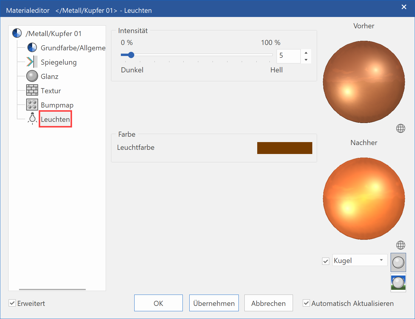
Intensity
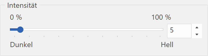
Use this slider to define the intensity of the illumination.
Colour
A special "light colour" can be selected that can be different from the base colour. The standard Windows colour dialog opens.
Tip
The option COLOUR is only visible if the "Extended" check box is activated.
Shadow
You can set the shadow parameters of a material here.
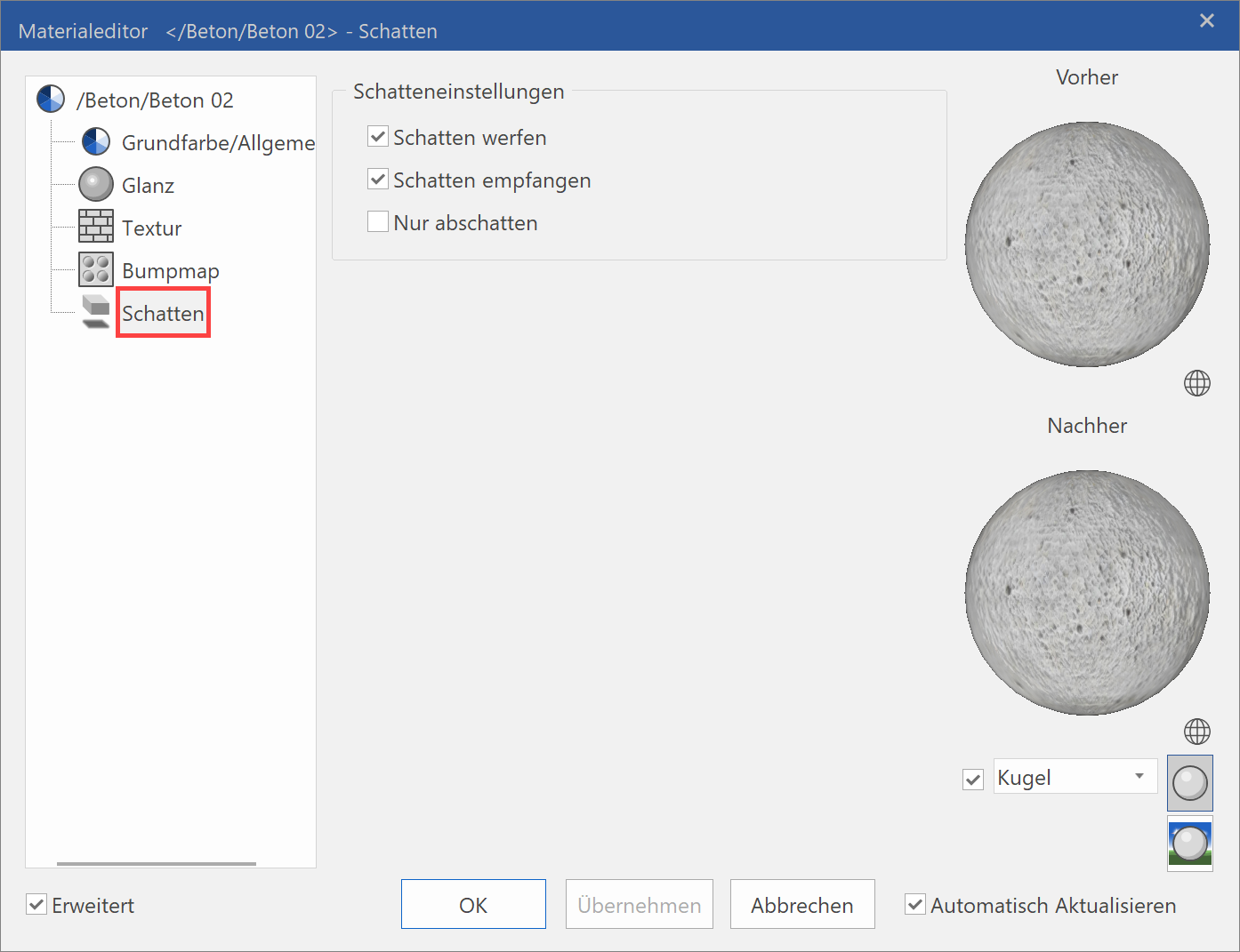
Cast shadows
A material casts shadows if this option is selected.
Receive shadows
Shadows are cast on the material if this option is selected.
Shadowing only
If this option is selected, the material is switched to transparent but still receives shadows if the option RECEIVE SHADOWS is selected.
Tip
This option is especially suitable for displaying a shadow cast by 3D objects on a background. Draw a surface under the objects and allocate a material for which "Shadowing only" and "Receive shadows" is activated. The colour of the material should preferably be white.
| "Shadowing only" inactive | "Shadowing only" active |
|---|---|
 |
 |
Shader
Here you can set the shader parameters of a material.
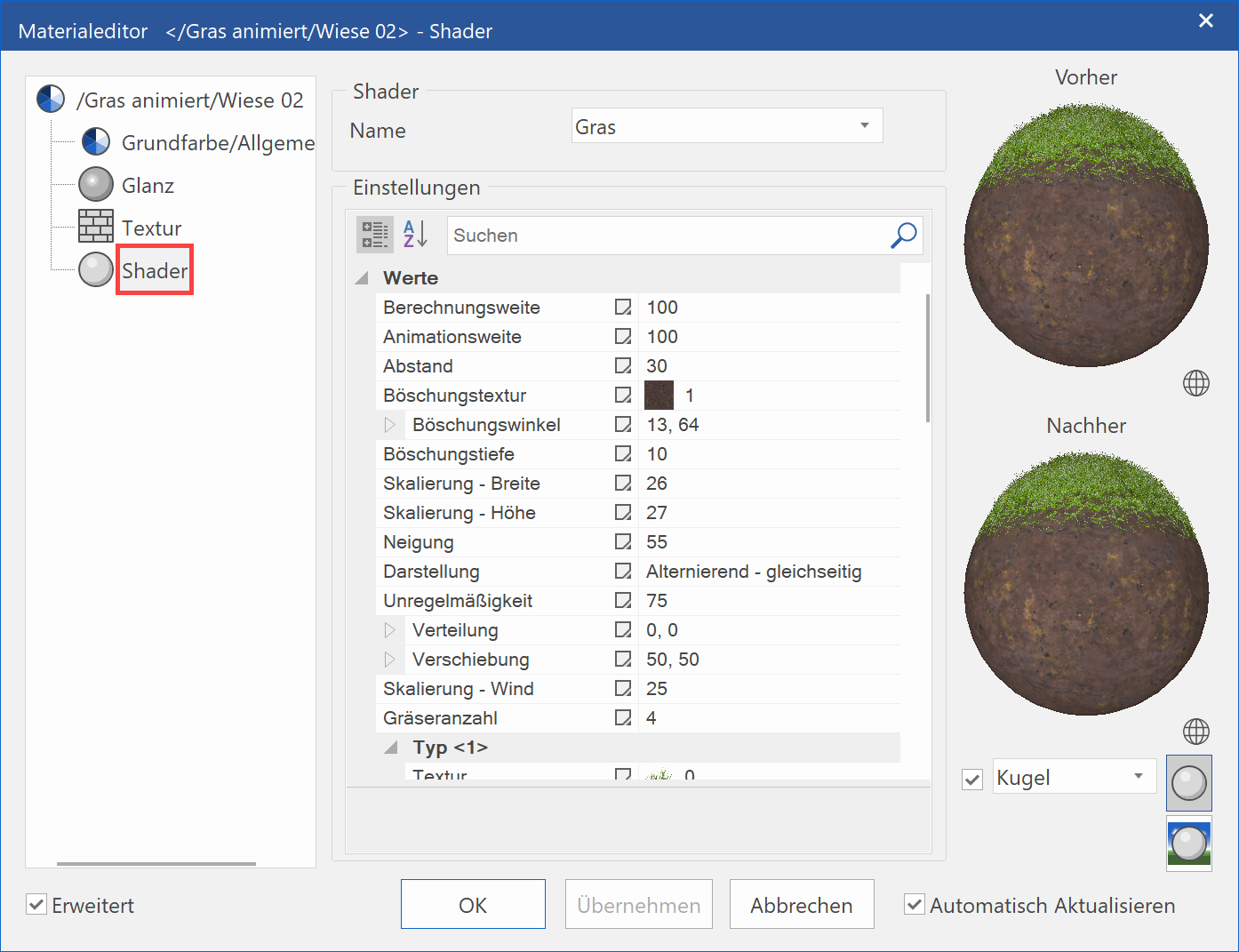
Shaders generate material visualisation on 3D surfaces in real-time. Surfaces with complex structures and depth effects are depicted on flat surfaces, which only need little memory. This process takes place on the graphics card and therefore enables huge performance gains.
Name
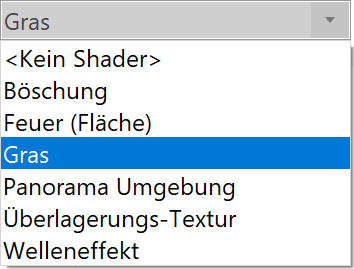
Here you can select the shader type. There is a predefined number of shaders for several material types available.
Settings
In this section, the parameters of the respective shaders are configured. The parameters displayed depend on the type of the shader.
Any changes in the parameters are immediately displayed in the preview window or in the model if the option is set.
Filter for parameters
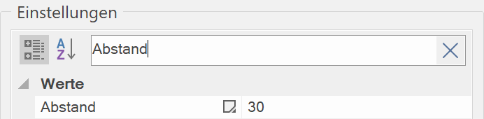
By entering a text, only the values, which fulfil the search criteria, are shown.
Values

In this area, a description of possible values of the selected parameter is displayed.