Input-/Status Bar
CAD input window

The input window contains the image properties, the information line, the input field and the status.
Image properties

These commands are fixed. They control how the data is displayed on the monitor. Zoom factor, cut-out, imaging, etc.
Information line
Input line
This line has a double function. It displays commands regarding what type of input you must enter or specify within a specific function. Use the entry line to forward information to the program. This information can be texts, coordinates or, in the event of queries, confirmations.
Status window


You can select scale, units, page format representation level (AR only), filter for renovation planning states(AR only) and view (ME only) here.
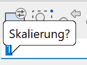
Status – scale
A free scale can be specified in addition to the predefined scales.
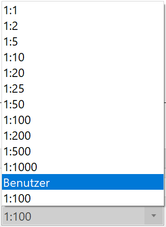
A free scale can be specified in addition to the predefined scales.
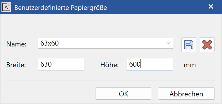
Status - format
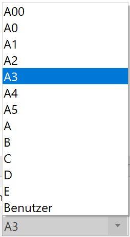
A user-defined format can be created by selecting "User". The special formats can be saved under a parameter name and reused at any time.
Status – filter for renovation planning state
(only ELITECAD Architecture)
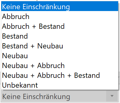
Several reasonable combinations of renovation planning states are predefined in this menu. By selecting one item all objects assigned to this state (combination) are shown.
Functions in the input line
The crosshair can be positioned using coordinate entries.
The Cartesian and polar coordinates system are available options.
Cartesian coordinate system: Lines x (X), y (Y) and z (Z)
Polar coordinates system: Polar angle a (A) and radius vector d (D)
Positive direction (direction of rotating) anticlockwise.

(x,y) and (a,d) written in lower case mean relative entry from the perspective of the current location. (X,Y) and (A,D) written in upper case mean absolute entry from the perspective of the absolute reference point (e.g. centre of page). It is also possible to combine relative and absolute coordinates. The system recognises the difference between x and y values by setting a separator sign.
The separator signs for list values and decimal numbers are defined in OPTIONS. The default sign for lists of values is the comma, for decimal number the point.
The system is set to relative coordinates by default.
Entering special characters

If the right mouse button is pressed above the entry line on "??", a selection of special characters appears.
The character can be copied into a different dialog window using the clipboard.
Copy: Ctrl + C
Insert: Ctrl + V
Not all character sets have all special characters.
Individual special characters can also be entered by holding down the Alt key and entering the corresponding ASCII number. The number must be entered using the numeric keypad (usually on the right of the keyboard).
Examples:
Alt + 1 + 5 + 5 produces "ø" (small diameter character) after releasing the Alt key.
Alt + 2 + 4 + 1 produces "±" (plus-minus sign) after releasing the Alt key.
Status bar

The left-hand area shows confirmations, e.g. that the data was saved successfully. The active work plane is positioned to the far right. "Z" stands for axis; "-10" indicates the height on this axis.
In ELITECAD Architecture, for example, these coordinates would be in the upper storey, "Z270", and in the basement "Z-260".
If working with classification is active, then the classification (model, group, class, level) from the active object is displayed in the status bar.