Representation Level
The display of the 3D and architecture objects in the floor plan and section is controlled by using representation levels. The appearance and label of windows and doors, room stamps and architectural dimensioning vary according to the selected representation level.
The representation level does not need to be automatically linked to the scale but can be selected according to the planning stage (design, permission, execution, etc.). These planning stages are of course linked to a certain SCALE setting, so the hatch, text and dimension parameter settings as well as the precision of the details of the AR Objects must be taken into account accordingly.
Select representation level
The representation level is defined in the status bar:
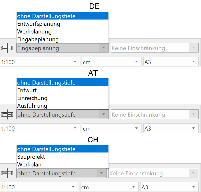
The state "without representation level" specifies that the file will be worked on without representation levels. The possibility of implementing the planning stages "at the touch of a button" from the entry planning to the work drawing, for example, is then no longer available. The settings of the respective functions are used under "without representation level".
Representation level settings
|
|
Settings toolbar |
| Menu > Settings > Representation levels… |
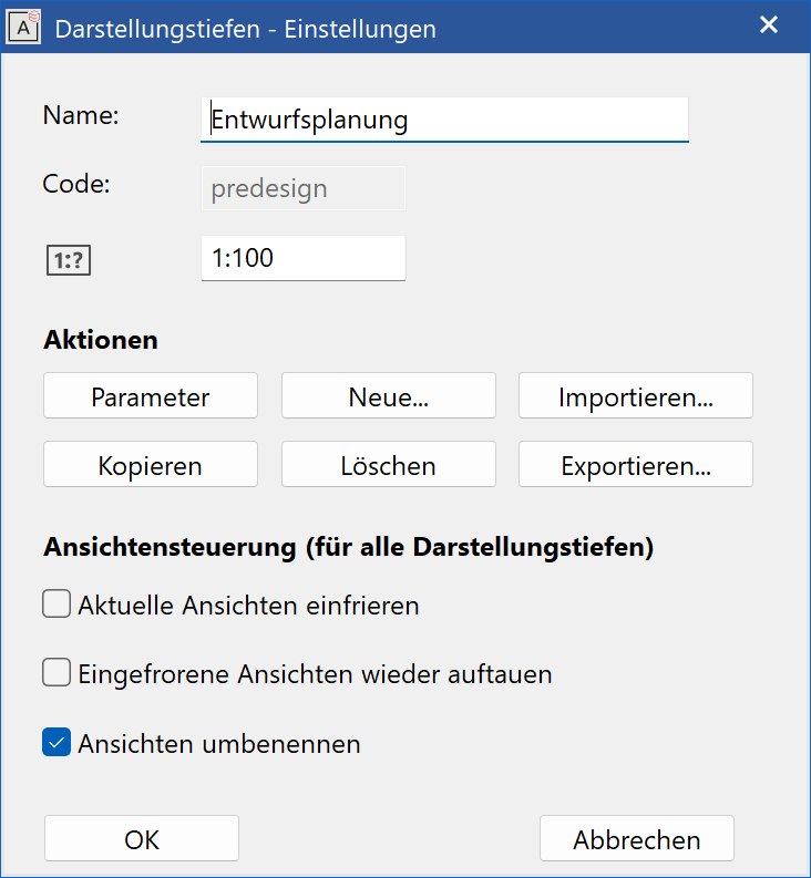
The fields Name, Code and Scale represent the values of the active representation level. The code is a unique characteristic as the names of the representation levels mostly stay the same during import or export.
Parameters
The detailed settings of the active representation level.
New…
Creates a new EMPTY representation level. Check whether it is easier to use the COPY function and then make changes. When creating a representation level, the parameter's storage type under SETTINGS > OPTIONS > SYSTEM > CONFIGURATION determines whether the representation level is created for User or Global.
Copy
Creates a new representation level with the same settings as the active representation level.
Delete
Removes the active representation level. If the message "not authorised" appears when you delete a representation level, this means that in this case it is a global representation level, which can only be removed by an administrator.
Import
You can import a representation level using this function. This way, a representation level that you have created yourself can be imported on different workstations.
Export
Using this function, a representation level can be saved and imported for use on other workstations.
When creating a new file, a dialog window opens in which the name, a unique code and optional scale for the representation level must be entered.
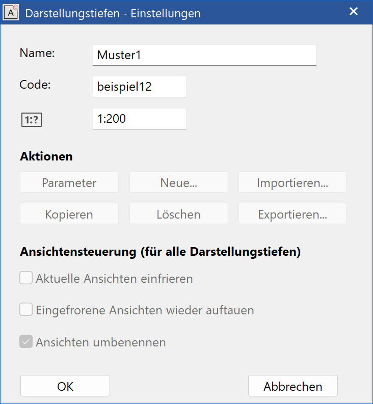
 creates the name of the representation level. All specified materials (accessible via the Parameters button) are adopted into the new representation level and must now be adjusted according to your needs.
Parameters

Clicking the parameter icon, takes you to the settings dialog window of the active representation level (see display in Status-Window).
Materials manager
The line widths and hatch parameters used to display the materials of walls, floors, girders, chimneys, stairs and columns in the floor plan and section views are defined in materials management.
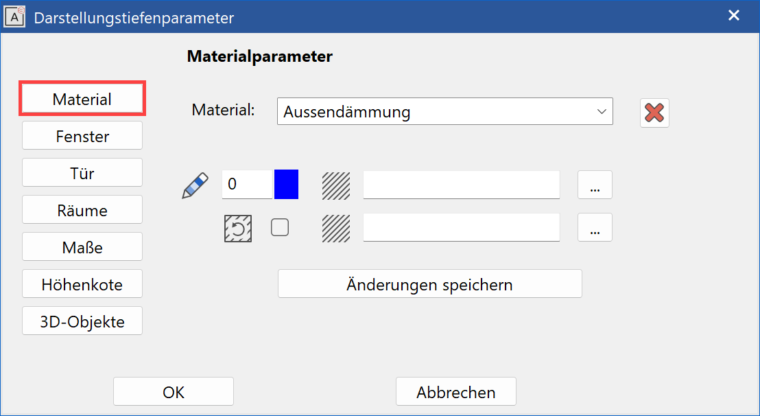
Existing materials can be selected from the selection box where the pen and hatch parameters always refer to the active material. The hatch parameter can be selected from  i.e. from a list of all of the settings created under Hatch – Parameter. If the hatch field is empty, no hatch is implemented.
Materials can also consist of two hatches: a grey preview hatch and a line hatch over it.
If this option is activated, the hatch rotates with the material.

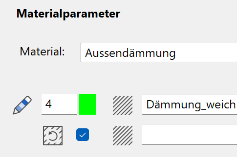
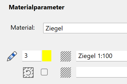
The "insulation" material rotates with the wall; the "brick" material does not.
Should a new material be created, you can enter the desired name into the selection box, specify the pen and hatch parameters and confirm with <Save modifications>. This material name is now also available in all of the other representation levels and can be individually customised for each representation level.
<Delete> removes the active material from all representation levels.
Window parameters
The settings for displaying windows in 2D and 3D can be defined here. In addition, you can also modify the type of label and the text parameters to be used, the length and the pen for the centre line, and the pen and line types for the lintel lines.
Depiction
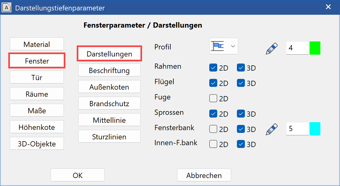
The window profile can be generated in the floor plan as a simple 2D line, frame or off-centre frame depiction, in which the lines for the frame, casement and dummy frame/joint (different gross clearance/finished clearance) can be switched on or off and whose pens can be changed. The 3D depiction for frame, muntins, exterior and interior windowsills is individually selected.
Label
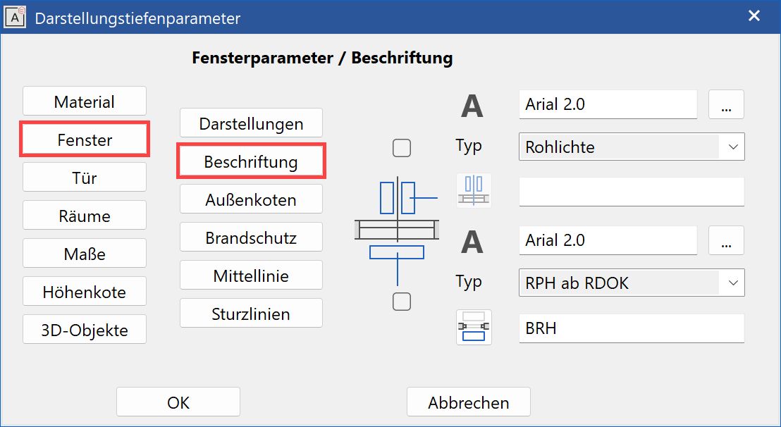
The centre line dimensioning of the window size can be depicted with either the gross or finished clearance or as an absolute marker for the parapet and lower edge of the lintel (Swiss standard).
The parapet height's label is toggled between the gross or finished parapet and the text formatting is entered (< > is the placeholder for the value). Please also refer to Window-Label parameters.
Under  you can select the text parameters to be used (all of the settings are set under Text parameters).
In addition, you can deactivate the label of the size entry and parapet height (check boxes).
Fire proofing
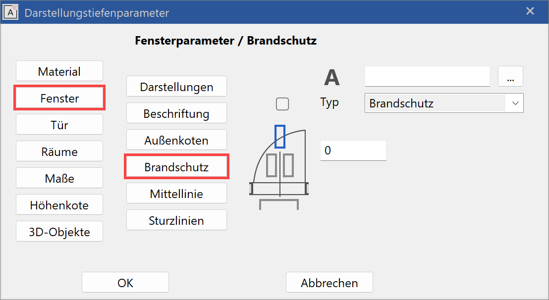
Windows have the option for fire proofing labelling. Any symbol that follows the tilde "~" symbol, will be depicted subscripted. The tilde symbol itself is not depicted.
You can select the text parameters to use under  .
.
In addition, you can deactivate the label of the size entry and lintel height (check boxes).
Height markers
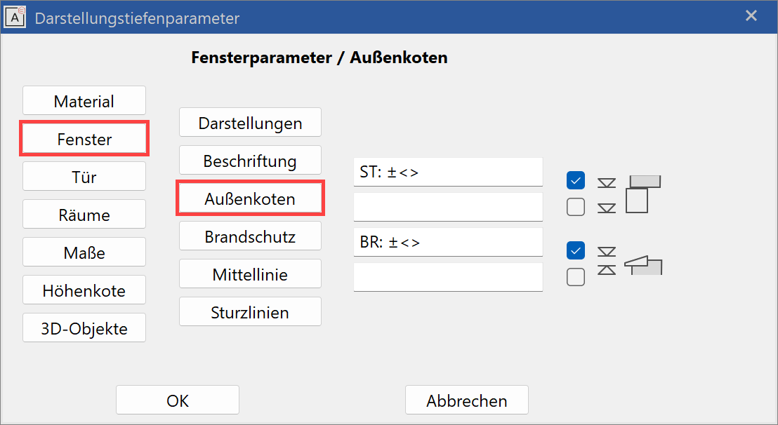
If the windows are created with height markers, you can specify here which markers are to be written with which text. The characters < > are placeholders for the calculated value.
Centre line
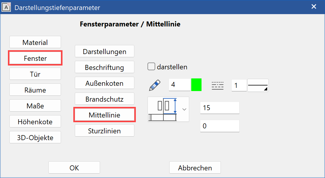
The length of the centre line can be defined in absolute lengths or as a distance dimension to the label text. The value of this is always given on the plan in mm. The depiction of the centre line can be switched off using the tick box, however the length of the centre line applies to the distance of the label to the wall outer edge, even when it is not displayed.
Lintel lines
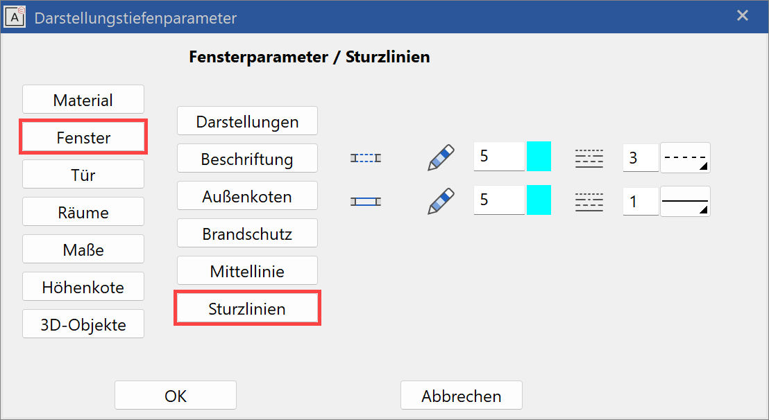
Here you can set the pen and line types of the lintel lines for the hidden and visible depiction (see window lintel).
You can then preserve dashed lintel lines in, for example, a window without parapet in one representation level and not in another representation level (with pen 0 = not printed).
Door parameters
The settings for the depiction of doors in 2D and 3D can be defined here. In addition, you can also set the type of label and the text parameters to be used, the length and the pen for the centre line, and the pen and line types for the lintel lines.
Depiction
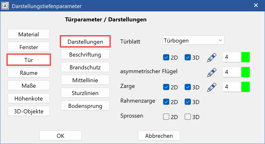
Door leaf and door jamb can be depicted in either 2D or 3D. The door's split level line (stop line) can be configured with the pen/line type and can be suppressed. The split level line can then be shown or suppressed in a representation level.
Label
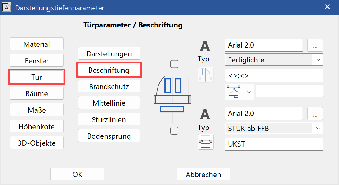
The centre line dimensioning of the door size can be depicted with either the gross or finished clearance, in floor clearance (TSFFL up to LS lintel) or as an absolute marker for threshold and lower edge of the lintel (Swiss standard). The lintel height's label is toggled between gross or net lintel height or lintel (gross) FFL and the text formatting is entered (< > is the placeholder for the value).
Fire proofing
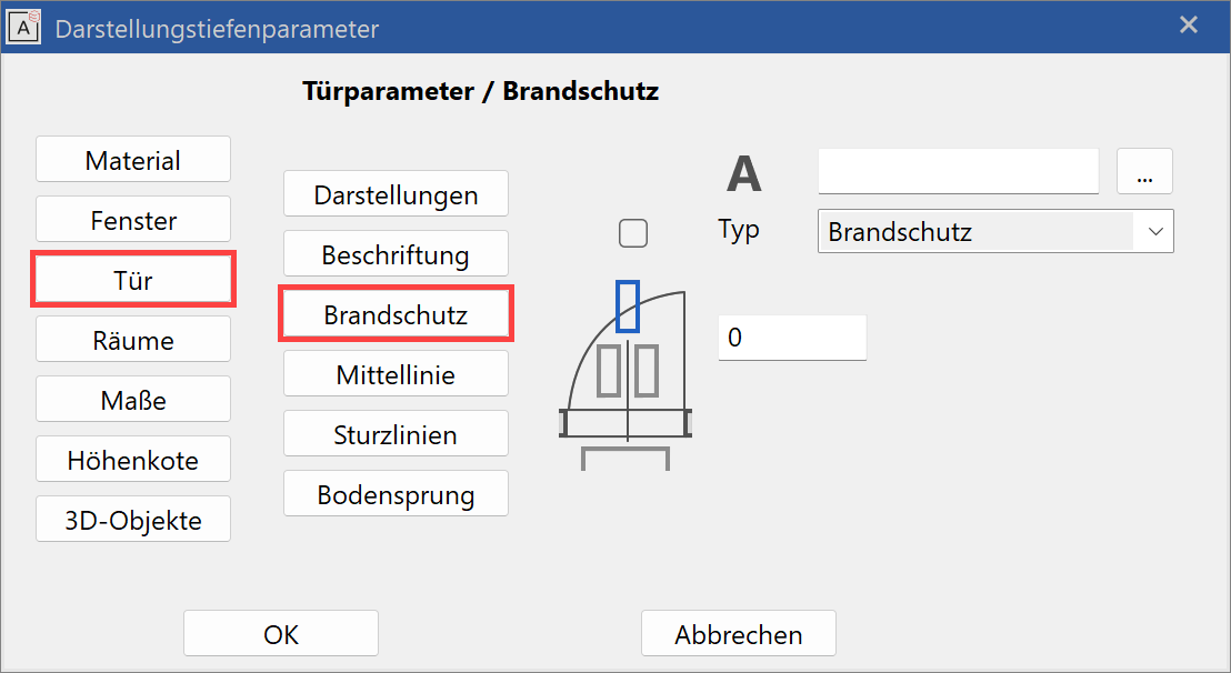
Doors have the option for fire proofing labelling. Any symbol that follows the tilde "~" symbol, will be depicted subscripted. The tilde symbol itself is not depicted.
You can select the text parameters to use under  .
.
In addition, you can deactivate the label of the size entry and lintel height (check boxes).
Centre line
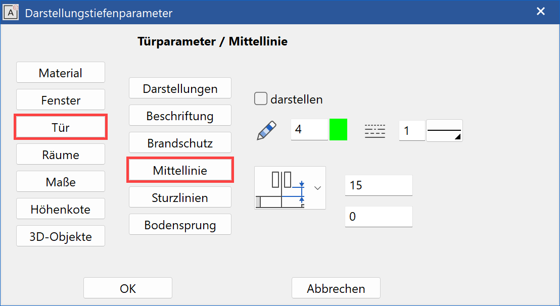
The length of the centre line can be defined in absolute lengths or as a distance dimension to the label text. The value of this is always given on the plan in mm. The depiction of the centre line can be switched off using the check box, however the length of the centre line applies to the distance of the label to the wall’s outer edge, even when it is not displayed.
Lintel lines
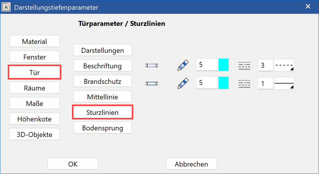
Here you can set the pen and line types of the lintel lines for the hidden and visible displays (see lintel).
You can then preserve dashed lintel lines in doors in one representation level and not in another representation level (with pen 0 = not printed).
Door split level line
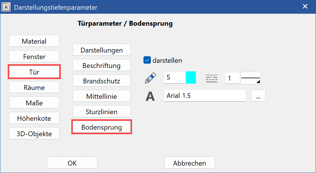
The door's split level line (stop line) can be configured with the pen/line type and can be suppressed. The split level line can then be shown or suppressed in a representation level.
Room parameters
Room labels and room groups are linked with the representation level. The parameter name defines the label parameter saved under the ROOM function. This is also true of the ROOM GROUP.
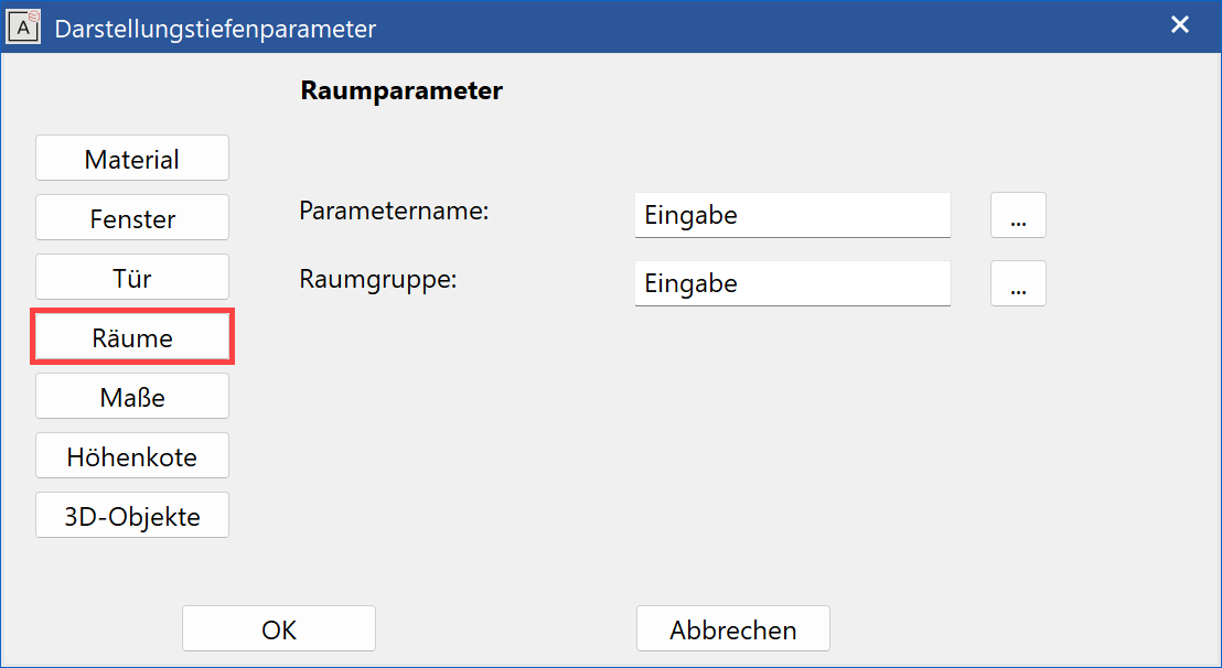
You can select the desired parameter under  . The set parameters for the ROOM and ROOM GROUP functions are loaded when the representation level is converted.
Dimension parameters
In this dialog window, you specify the dimension parameters for the parameter group 1-3 to be used during architectural dimensioning.
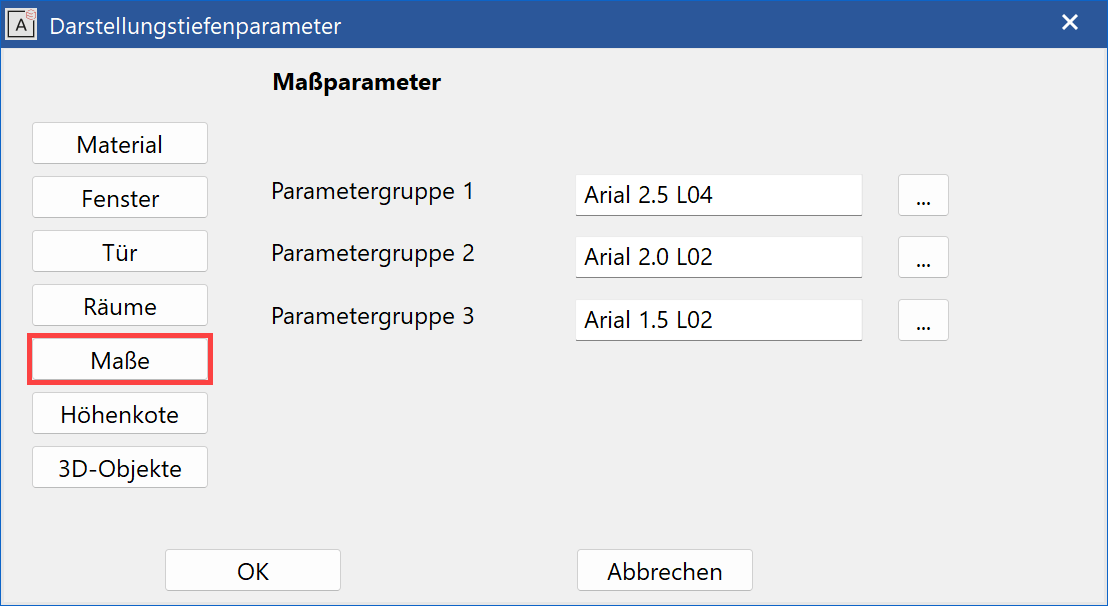
The dimension parameter must be selected from  , i.e. from a list of all of the settings created under the function DIMENSION PARAMETERS > PARAMETER NAME. Selecting a representation level automatically converts the active dimension parameter.
The three parameter records are linked with the parameter groups P1, P2, P3 in the dimension property bar.

Height marker parameters
Improved · 16 R1 · Improvements
In this dialog window, you specify the dimension parameters for the parameter group 1-3 to be used for height markers and floor plan height markers.
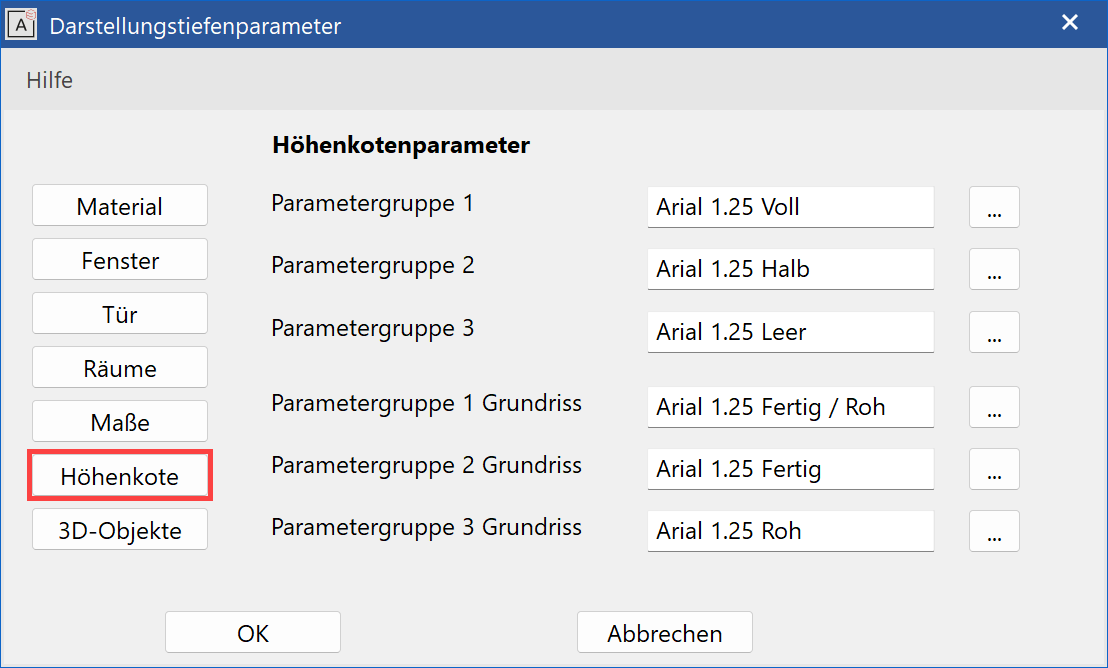
The text parameter must be selected from  , i.e. from a list of all of the settings created under the function TEXT PARAMETERS > PARAMETER NAME. Selecting a representation level automatically converts the active text parameter.
The three parameter records are linked with the parameter groups P1, P2, P3 in the height marker and floor plan height marker property bar.


3D-Objects
Free 3D definitions (box, trans boxes, etc.) are subject to the representation level and therefore allow a depiction that is true to the material for views, sections and floor plans at the appropriate scale.
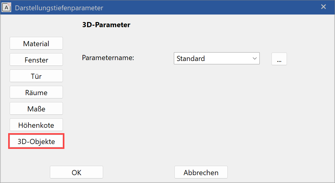
You can select the desired parameter under "Parameter name". This preset parameter is then loaded for the 3D objects, which are linked to the representation level when the representation level is switched.
The detail settings can be called up directly under  .
.
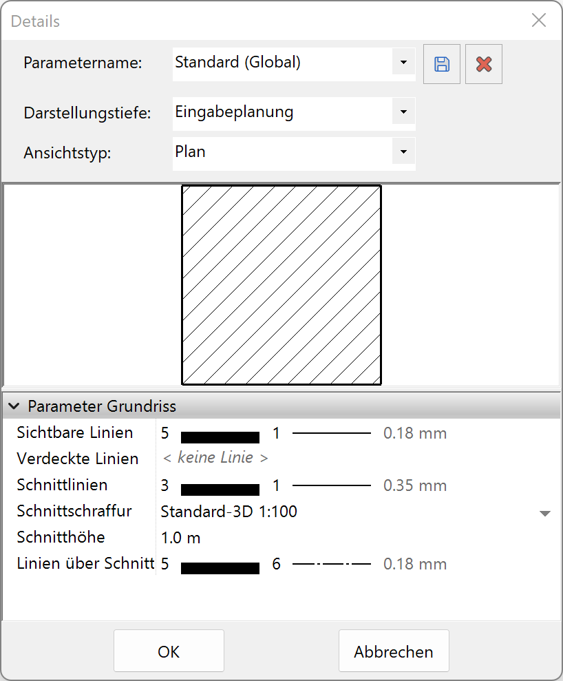
With this dialog, existing templates can be modified or new ones defined. The settings can be made for all representation levels.
Refresh representation level

If a drawing is loaded and the representation level is changed under the status list, you can select what should be refreshed in the Refresh representation level dialog window.
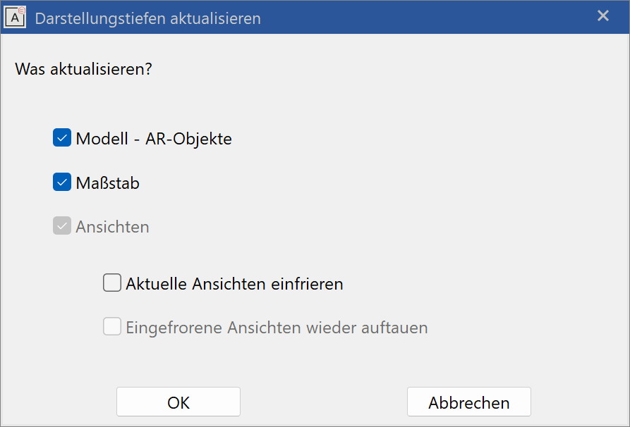
If you would like to refresh a representation level without converting it, click the parameter button to access this dialog window.
Design model – AR-Objects
All architecture objects such as walls, windows, doors, etc. are generated anew in the selected representation level.
Scale
If a default scale is specified for the representation level, you can decide here whether another scale should be used for the refresh. The scale can also be retroactively adjusted in the status line.
Views
Material depictions and architectural dimensions are updated in the views and sections with the selected representation level's settings.
Freeze active views
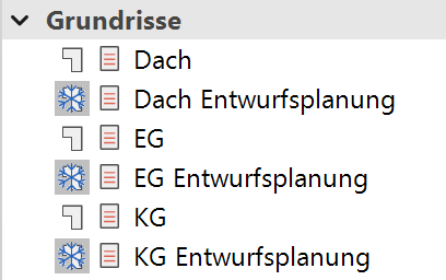
When activated, all existing views of the view, section, plan, detail and plot type are frozen in the active state.
These views are specially marked with a frozen symbol in the views manager and additionally retain the representation level's description in their names.
Frozen views (except for the plot views) cannot be refreshed.
If the representation level has been changed and modifications to the design model have been made, selecting Refresh view can bring a frozen plot view back to its active state.
If you try to refresh a frozen view of the section or plan type, the following message appears:
View is OFFLINE!
Release frozen views
To return to an already existing representation level, unfreeze and refresh the already created views.
Should the state of the existing views remain the same, deactivate the switch. If the representation level then changes back and the views are again frozen, the marker _1 is added to the name.