Structure
What is a structure?
A structure is treated as a continuous and self-contained building in ELITECAD. The structure can be comprised of multiple storeys but this is not a necessity. The classification into different structures allows you to manage buildings with different height levels. Two structures can both have an upper storey named "NF1" on differing levels.
Structures are generally used as filters. They can be understood as a combination of the different storeys, which can be selected separately. This creates a variety of possibilities for the editing of the design model, as well as by several co-workers. The structure "without structures" is automatically assigned to all of the drawing objects to which the program cannot assign a unique structure (or storey).
Tip
The division of the building project into different structures should be carefully considered. On the one hand, separated buildings create a better structuring of the project, but on the other hand it is not very useful to divide a building with shifted floor levels in one storey into two structures, for instance (...which of the two do the continuous exterior walls belong to?).
Structure settings
|
|
Storeys manager > Project settings |
| File menu > Structure settings |
Creating a new project opens the structure settings dialog window, which can also be called up any time during editing from the storeys manager.
The dialog window is comprised of four different entry ranges:
Structure, Height section, Storeys and Buildings.
The  button saves and quits the dialog window;
  also saves the entries but does not close the dialog window.
Tip
Should the entered values be saved as standard, the option SAVE AS DEFAULT in the FUNCTIONS menu should to be used. (See description below)
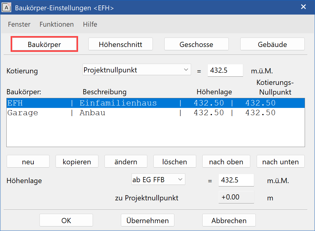
Structure
This entry range consists of four parts.
- The general height marking of the project
- The list of structures
- Commands to create and modify the structure
- Height reference (±0.00) and height situation of the single structures
Entries and modifications always refer to the active structures, even in the other entry ranges. This is shown in the title of the structure dialog window and ELITECAD window.
Height marking
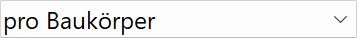
Three different settings are possible:
- Sea level: The structure's height situation is relative to altitude.
- Project null: The +/- 0.00 corresponds to the height of a select reference point.
- Per structure: Every structure has its own height situation.
 |
 |
 |
|---|---|---|
 |
 |
 |
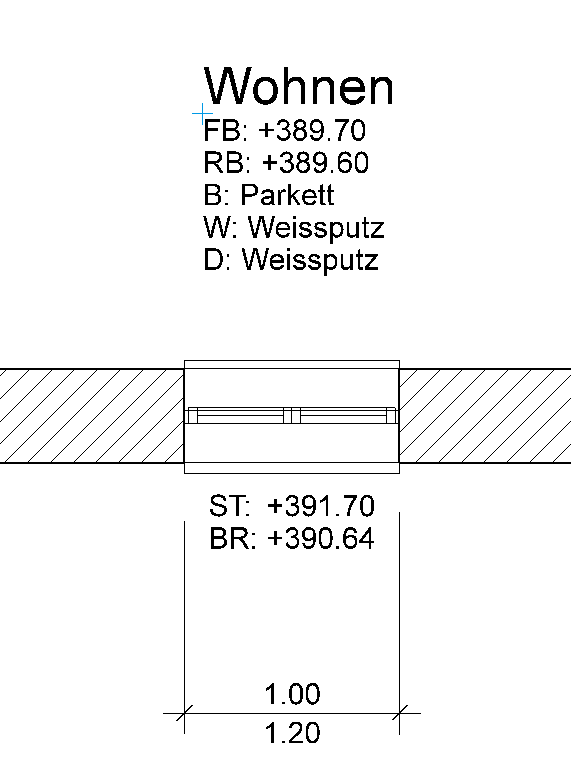
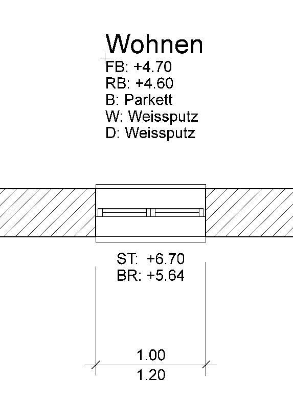
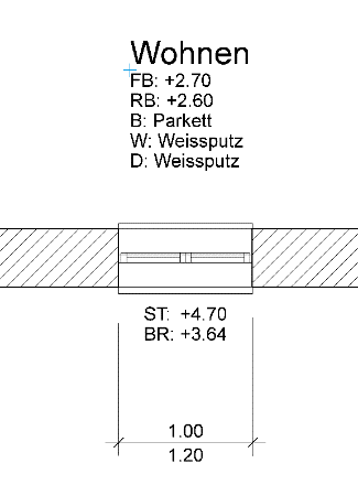
This information only affects the automatic height marking of the window and room label.
Structure list
Defined structures are shown here with their main properties.
You can easily activate the desired structure by selecting it from the list. If different structures are created with differing height situations, a difference in level for this to the project null, which can be read in the grey-shaded field, appears.
Tip
At a later point in time, if it becomes necessary to modify the height of the project null, the reference heights of the individual structures must be adjusted accordingly.
Commands to create and modify the structure
New/modify
This function opens the parameter dialog window of the structure settings in order to either create a new structure or amend the values of an existing structure.
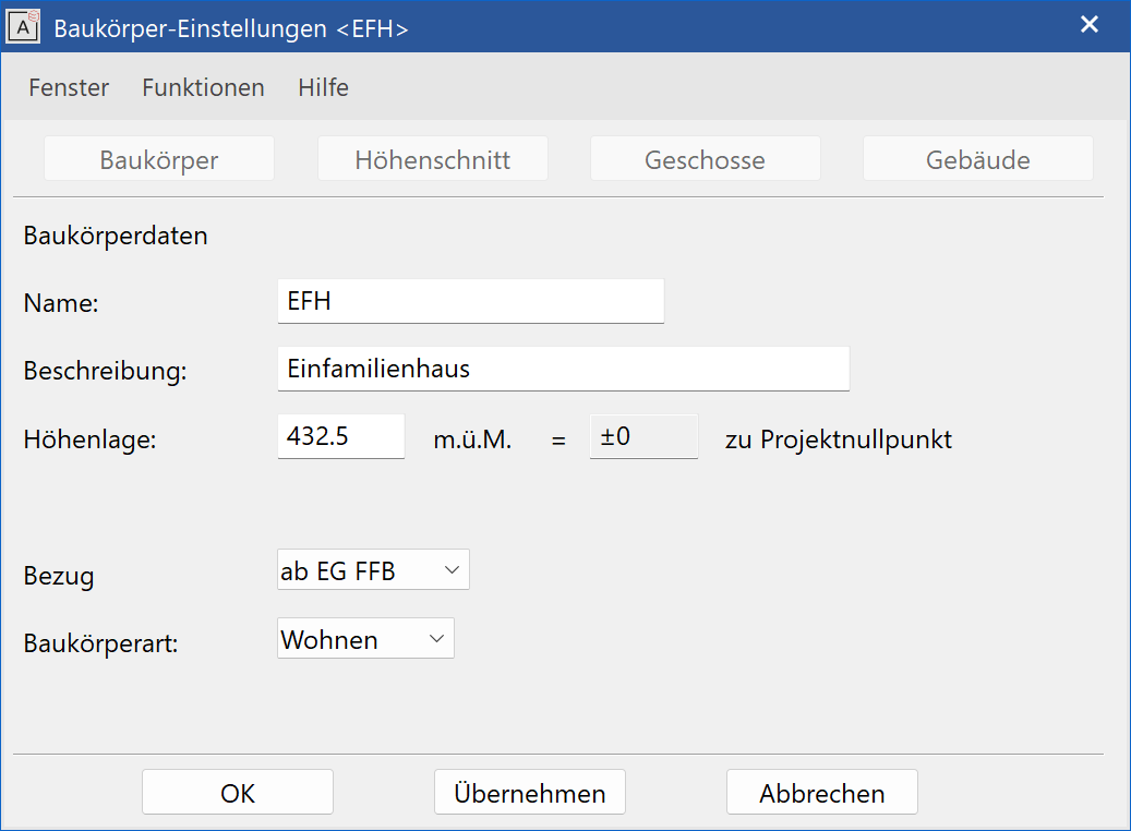
Name
The name appears in both the settings dialog window and in the quick info in the storeys manager window. It is therefore worth choosing a short and unambiguous term. A new structure is automatically called "new" when it is first created.
Description
This information is used to clarify the chosen name. This only appears in the structure settings overview.
Height situation
The height situation can be entered here and the difference in level to project null can be read in the grey-shaded field.
Reference
With this switch, you can specify whether the +/- 0.00 is located on the finished floor level (FFL) or on the ground floor's bare ceiling TS (BCTS).
Type of structure
This dropdown menu selects a building type for the structure. Standard heights then appear in the Height section entry range (if such had been entered via the Building entry tab).
Either or confirms the information and the display switches to the Height section entry tab.
Delete
Deletes the selected structure's data from the list provided, so that it contains no elements.
Copy
Creates a copy of the active structure settings with the same name+1.
Upwards/downwards
The buttons UPWARDS and DOWNWARDS sort the structures. Sorting these in descending order also applies for sorting the storey manager from left to right.
Height reference (±0.00) and height situation of the single structures
You can specify the active structure's height reference and height situation here. The difference in level to the project null is shown in the grey-shaded field.
Height section
You can specify the number of storeys as well as their height for the active structures with this entry tab. All information is entered in the "active unit"; only the ridge height and the maximal building height are always entered in[m].
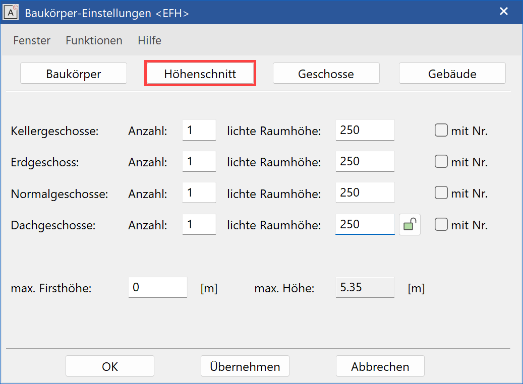
Number
Enter the number of the same type of storey here. The possibility of being able to define multiple ground floors is used to manage differing height levels within the structure.
Height
Enter the standard value for the room clearance (FFL to lower edge false ceiling) of each type of storey here.
Tip
In contrast to the room height clearance, the dimensions for the "installation height" and "floor finish" are included for the framing height clearance. These values are defined in the entry tab: Storeys.
With no.
This function provides the storeys with a consecutive number to reach the same storey description. If you have a project with two structures and one of the two only has one normal storey, the active numbering identifies the storey as "NF1" instead of "NF".
"Lock" – Controlling the height of multiple storeys of the same type
The number of similar storeys can be entered in the height section.
If the room clearance of such storeys differs from the values of the height section, a green lock appears next to the Height field.
The lock has two functions:
If the lock is closed with a click (colour switches to red) and the entry is confirmed with , all room heights in the entry range "Storeys" are reset to the height section's standard values.
E.g.: The value for NF1-NF3 = 3 m but all values in NF4 = 4 m are then reset to 3 m.
If the lock stays open and a new height is entered into the entry field and confirmed with , the net clearance of all of this type of storey is changed by the difference between the old and new value.
E.g.: If NF2 is increased from 3 m to 3.50 m, then all storeys are increased by 0.50 m.
Maximal ridge height and maximal height
The heights of all of the active storeys above FFL GF is shown in the max. height field. A warning appears if it is higher than the max. entered ridge height.
If the entered height indication as well as the settings from Building should be available by default, these can be saved with the "Type of structure" under FUNCTIONS > SAVE AS DEFAULT. These settings are once automatically filled in when a new structure is created when the relevant type of structure is selected.
In addition, please read the paragraph on the graphical height section below.
Building
The presettings for the active structure can be specified in the entry tab Building. The values assigned here can be overwritten at any time.
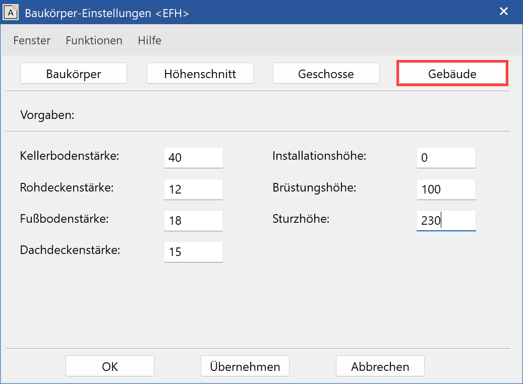
Thickness for walls and columns
General construction data for active types of structure can be noted here. The information is solely for documentation purposes and has no effect on the design model.
Presets
These values are suggested for the height section's settings.
Basement floor thickness/raw slab thickness
The information describes the slab's framing dimension.
Floor thickness
The value stands for the floor finish. This is the dimension from the structural floor level (BS) to the finished floor level (FFL).
Installation height
The value stands for the height of the false ceiling construction.
Parapet height/lintel height
These values are used for the AR OBJECTS > FACADE GRID function.
writes the data into the project database and allows you to continue editing the structure settings' sub-dialog window.
Storeys
If the information under the height section is finalised with , these standard values are also available in the Storeys entry tab.
Now you can specify the single storeys more precisely if needed. Select the desired storey from the dropdown box. The "Type = standard" entry refers to the storey that has been entered into the height section; "Type = free" means that it has been set by the INSERT function.
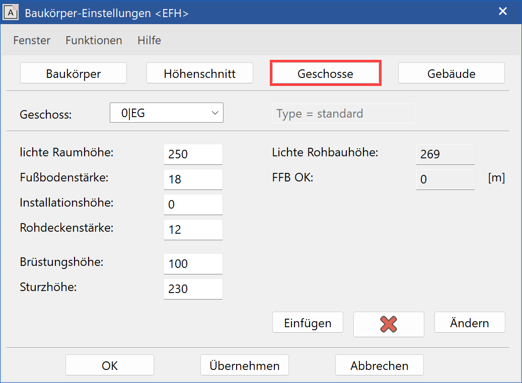
Room clearance
This information is finished measurements (FFL to lower edge gross ceiling).
Floor thickness
The value stands for the floor finish. This is the dimension from the structural floor level (BS) to the finished floor level (FFL).
FFL:
The height of the finished floor in the active storey is shown on the right-hand side of the page.
Installation height
The value stands for the height of the false ceiling construction.
Raw slab thickness
Always enter the ceiling of the storey located below in the field. As a rule, this belongs to the respective storey.
Label and lintel height
The information is for framing dimensions.
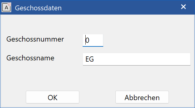
Insert
This function inserts a new storey between existing storeys or at the end of the list. The storey number (level) and storey name are to be entered in the entry line and the values for the new storey completed in the storey dialog window. Free storey descriptions can be used here (GF instead of BA; gallery or similar).
Delete
This function deletes a storey from the storey dialog window if it is empty, meaning that no elements are linked to it.
Modify
With MODIFY you can amend the "Storey number" (level) as well as the "Storey name". If a storey number has already been assigned, the current storey is given this number and the other is moved to a different position. Your own storey descriptions, for instance, can be used here (GF instead of BA; gallery or the like).
After modification, the design model is updated automatically.
If the design model had not been loaded at the time of the modification, a query appears when loading that the structure settings are different if the option QUERY IF STRUCTURE SETTINGS DO NOT MATCH under SETTING > OPTIONS > SAVE/LOAD > GENERAL has been selected. If the dialog is not displayed, the settings from drawing are applied.
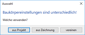
This dialog also appears when you load a drawing from a previous project, which does not match that of the active one.
If from project is selected, the design model is automatically refreshed according to the new parameters. All walls, windows, doors, columns, ceilings and roofs, which refer to the height section, are adjusted in level and height.
If from drawing is selected, the active project settings are overwritten by the project settings saved in the drawing. The drawing will then be loaded, as it has been saved.
If join is selected, the drawing is loaded as it was saved, the modified structure appears in manager as before but is renamed as [Structure name]1
If drawing A had fewer structures than the previously loaded drawing B from the same project, the storeys manager specifies the difference and queries whether the unmodified structure(s) should be deleted or whether it must be kept (as an empty structure).
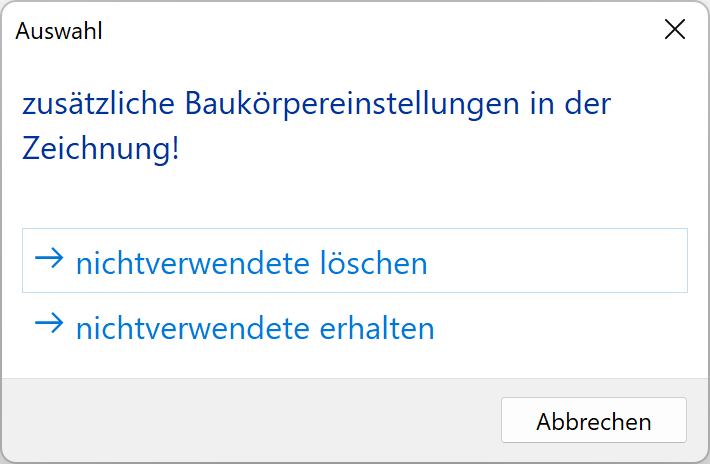
This dialog appears if the option QUERY IF STRUCTURE SETTINGS DO NOT MATCH under SETTING > OPTIONS > SAVE/LOAD > GENERAL has been selected. If the dialog is not displayed, the unused structures are deleted.
Functions
Different commands are available in the FUNCTIONS menu:
Save as default
This function saves all of the structure's settings but of course without the list and number of storeys. In this way, the settings, which have been made once, can be predefined for future projects. These default settings are saved for every selected type of structure (entry tab STRUCTURE > MODIFY > TYPE OF STRUCTURE).
Modify in image
This function will be described below in "Graphical height section".
Regenerate storey dialog window
This function calculates a new height section from the starting values of the Height section and Building. If, for example, the thickness of all raw ceilings in the project is modified, this value can be modified in the Building entry tab and generally assigned via the Refresh storey dialog window.
Graphical height section
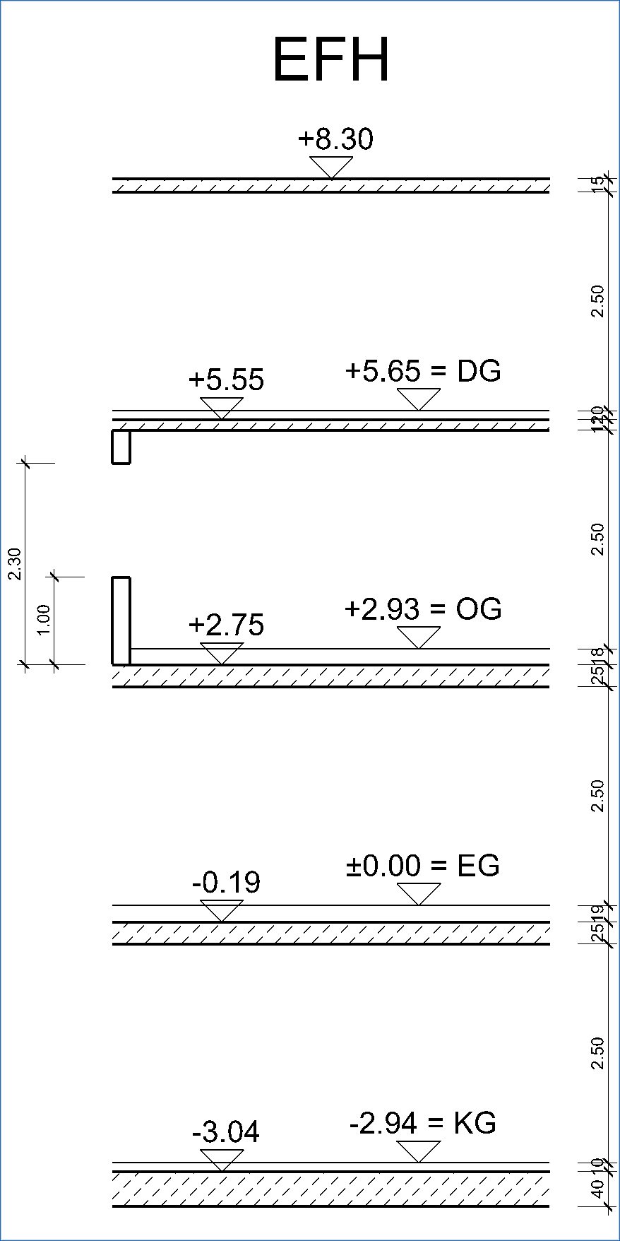
By selecting the function MODIFY IN IMAGE under the FUNCTIONS menu and clicking the concerned parts in the graphic, the storey values can be modified.
Tip
Type near a graphic depiction, e.g. the parapet: You can now modify the value of the parapet height in the entry line. This is also true when you click on the dimension figure for the parapet height. The data in the storey settings is automatically refreshed and the height section is adjusted.
Create structure
|
|
Storeys manager; AR Object toolbar |
| AR Objects menu > Structure |
The CREATE STRUCTURE function generates a building volume from the storey ceiling and/or outer walls based on the structure settings and an outline and optionally creates the dimensions.
The outline must be from a closed polygon, which was previously defined. It does not matter to which storey the outline belongs. A storey of the desired structure must be active when the CREATE STRUCTURE function is started.

Parameter
![]()
Predefined parameter sets can be selected for walls and slabs by their names. This option offers the possibility for the usage of multi-layered components.
Layer
![]()
Choice of relevant layer.
Material
![]()
The material is defined in the representation level by a pen and hatch. A suitable depiction of the construction part is mapped in the plan.
Texture / 3D-Colour
![]() /
/ ![]()
A texture or 3D colour can be assigned for walls and ceilings.
Switch on/off
![]()
![]()
The walls can be switched off for a skeleton construction.
Offset ceiling
![]()
The ceilings can be allocated an offset, which resets the value.
Dimension parameter group
![]()
This selection is only available if a representation level is active.
Dimensions
![]()
Depending on the choice, up to three different dimensions can be selected.
Dimension offset
![]()
![]()
The offset to the wall and between dimensions can be entered here.