Break Views
This function is only available in ELITECAD Mechanics. Uniform long work pieces can be depicted in a shortened mode. Shortening positions are represented as tear-lines, which are drawn as zigzag lines, shaft- or pipe tear-lines.
In order to create a view shortening, the desired view has to be selected in the plot view first. Start the function via the menu LAY-OUT > TEAR LINE or via menu entry TEAR LINE in the context menu that opens by a click with the right mouse button in the graphics window.
Existing tear-lines are edited from the context menu entry EDIT TEAR-LINE or deleted from the context menu entry DELETE TEAR-LINE.
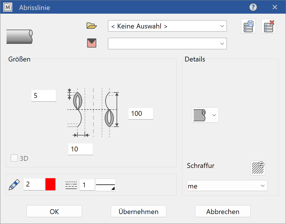
After starting the function, the following parameter window appears:
![]()
Once defined, parameters can be saved with SAVE RECORD under a chosen name and later reused.
The hatch for pipes and shafts can be selected too:
![]() shaft
shaft
![]() pipe
pipe
![]() zig-zag
zig-zag
![]() line
line
The hatch for pipes and shafts can be selected too.
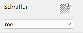 name of the hatch
In the main section of the window the dimensions are defined. Lengths and distances for the height of the tear-line, distances to the view shortening and the pipe thickness.
The fields in the lower section have the following meaning:
 tear-line pen
 tear-line line type
The completed dialog window is confirmed with  . A preview of the view shortening is displayed. Enter two points to define the position and the width of the shortening. The start- and endpoints of the tear-lines can be positioned by dragging with the mouse.
All settings can be edited afterwards using the same parameter window. Select the view shortening and select the symbol for editing or use the function EDIT TEAR-LINE.
Shortened views are only displayed shortened in plot views. If a view is activated for editing, the shortened region is displayed in its full extent.