Floor plans
In ELITECAD Architecture the floor plan displays the 2D-relevant architectural data of the model as a floor plan.
These are usually the drawing elements displayed in the plan graphics of a storey floor plan.
In ELITECAD Mechanics 3D floor plans are usually not used.
In ELITECAD Mechanics 2D a floor plan can be used to manage cut-outs of the model.
Unlike a section or a view, the floor plan always refreshes itself with the model and vice versa. If a door is moved in the floor plan, this modification is immediately visible in the design model.
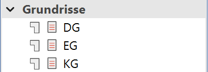
Each floor plan may have a separate visibility control of the layers. As such, there may be multiple floor plans of a storey in which different structures are visible.
Tip
The design model and the floor plan refresh each other. All floor plans are therefore always consistent with the latest version of the model. This is why lines from the 2D floor plan cannot be deleted arbitrarily without compromising the 3D geometry.
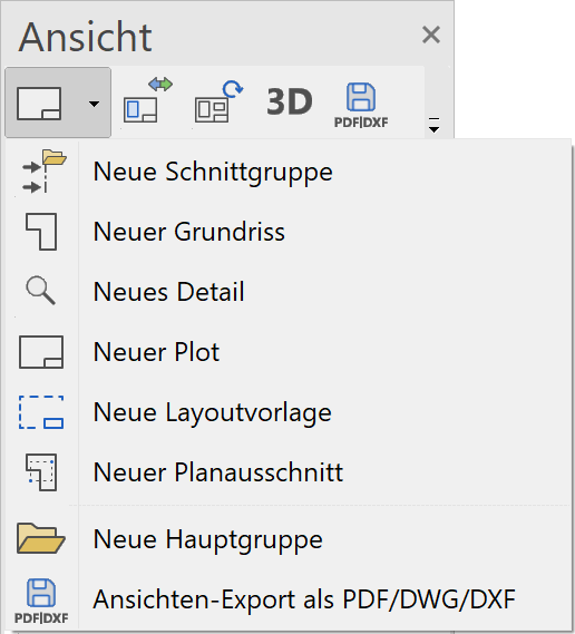
Header functions for the floor plans
| Function | Description |
|---|---|
| New section group | |
| New floor plan | |
| New detail | |
| New plot | |
| New layout template | |
| New plan cut-out | |
| New main group | |
| Modify | |
| Refresh | |
| 3D edit mode (only in ELITECAD Architecture) | |
| export as PDF/DWG/DXF | |
| Expand/Close all view groups |
Floor plan context menu
If you right-click on a created view, the following options are available:
Show view in a new window
![]() Details in OUTPUT > VIEWS > FUNCTIONS IN VIEWS.
Details in OUTPUT > VIEWS > FUNCTIONS IN VIEWS.
Float view window
![]() Details in OUTPUT > VIEWS > FUNCTIONS IN VIEWS.
Details in OUTPUT > VIEWS > FUNCTIONS IN VIEWS.
Rename
Details in OUTPUT > VIEWS > FUNCTIONS IN VIEWS.
Delete
![]() Details in OUTPUT > VIEWS > FUNCTIONS IN VIEWS.
Details in OUTPUT > VIEWS > FUNCTIONS IN VIEWS.
Create copy
Details in OUTPUT > VIEWS > FUNCTIONS IN VIEWS.
Refresh view
![]() Creates a new image assembly
Creates a new image assembly
Export view
![]() Details in OUTPUT > VIEWS > FUNCTIONS IN VIEWS.
Details in OUTPUT > VIEWS > FUNCTIONS IN VIEWS.
Save PDF file
![]() Details in OUTPUT > VIEWS > EXPORT VIEWS AS PDF/DWG/DXF.
Details in OUTPUT > VIEWS > EXPORT VIEWS AS PDF/DWG/DXF.
Modify view
![]() Details in OUTPUT > VIEWS > FUNCTIONS IN VIEWS.
Details in OUTPUT > VIEWS > FUNCTIONS IN VIEWS.
Generate floor plan views
|
|
Views manager > Generate floor plans |
| Insert menu > Floor plans views |
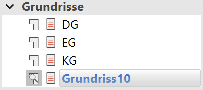
This function is only available in ELITECAD Architecture and creates all floor plan views of the model. Designation is performed in accordance with the designation of the individual structure settings of the individual storeys. All storeys that have the same storey number are displayed in the same floor plan view (e.g. "-1, 0, 1, 2") for multiple structures. If different storey names are on the same level, the individual plans are given the names "Level 0", "Level 1", "Level 2", etc.
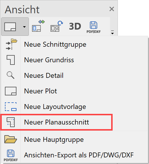
Create new floor plan
|
|
Views manager > New floor plan |
| Insert menu > View (plan type) |
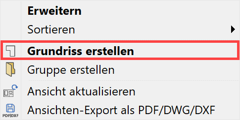
A new floor plan can be generated using the corresponding header function or from the context menu of the views if a model view is selected.
The desired settings have to be entered in the settings dialog window of the view. By clicking on  , the settings are saved and the view is created. The function MODIFY VIEW allows you to change the settings of the view after creation.
In ELITECAD Architecture floor plans are typically created by the function GENERATE FLOOR PLANS. The function CREATE NEW FLOOR PLAN can be used to define exactly which data appears in the plan. Each floor plan may have a separate visibility control of the layers. It is therefore possible to design multiple floor plans for the same storey with different contents (e.g. for electronic installation or furnishing).
Tip
You also have the option to display storeys from different structures in the same plan. E.g. Ground floor of structure A with the basement parking of structure B.
Settings of a floor plan
General parameters
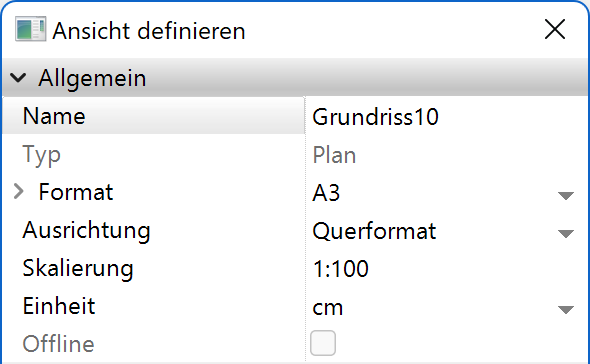
Name
Details in OUTPUT > VIEWS > GENERAL VIEW PARAMETERS.
Type
Details in OUTPUT > VIEWS > GENERAL VIEW PARAMETERS.
Format
Details in OUTPUT > VIEWS > GENERAL VIEW PARAMETERS.
Orientation
Details in OUTPUT > VIEWS > GENERAL VIEW PARAMETERS.
Offline
Details in OUTPUT > VIEWS > GENERAL VIEW PARAMETERS.
Plan parameters
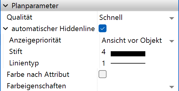
Automatic hidden line
This option is only available in ELITECAD Architecture. If a floor plan is defined with a storey filter, all 2D data belonging to the storey is displayed. In addition, a hidden line is created with this option for all 3D objects of the storey for which there are no 2D lines parallel to the storey level.
Colour by attribute
Details in OUTPUT > VIEWS > GENERAL VIEW PARAMETERS.
Colour scheme 
Improved · 16 R1 · Improvements
Details in OUTPUT > VIEWS > GENERAL VIEW PARAMETERS.
Renovation planning (only in ELITECAD Architecture)
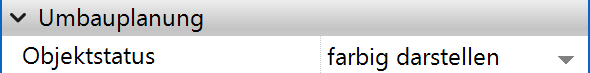
Object state
Details in OUTPUT > VIEWS > GENERAL VIEW PARAMETERS.
Fillings
Details in OUTPUT > VIEWS > GENERAL VIEW PARAMETERS.
Functions in the graphics window context menu
Define, modify or delete cut-out
Details in OUTPUT > VIEWS > FUNCTIONS IN VIEWS.
New plan cut-out
|
|
Views manager > Create plan cut-out |
The plan cut-out is an area of an entire plan. The plan cut-out is always up to date with the plan as well as the model. The plan cut-out behaves in the same way as a floor plan. Data that is added in a plan cut-out is also added directly into the plan and design model.
The plan cut-out is used if the floor plan has a format that is too large and must be divided into separate cut-outs for a printout. In ELITECAD Architecture, for example, an apartment building can be separated from the whole. The plan cut-out can be saved in a different scale than the floor plan. An area can be zoomed in when displayed on the border.
The plan cut-out can only be created from a floor plan. As soon as the floor plan is selected, the option NEW PLAN CUT-OUT appears in the header functions.
Once the name of the plan cut-out and the other settings have been defined, a property bar opens in which the line type and colour of the bordering can be determined. (Pen colour 0 = invisible on printout)
The cut-out in the plan is then defined via two diagonal points.
The plan section is listed in the floor plans.
The same editing rules apply as for the floor plans.
Tip
The detail frame should not be deleted from the original plan. The user therefore always has the option to stretch or move it and to refresh the plan cut-out again.
Navigate to origin
Clicking this function switches to the view in which the plan cut-out was defined. The visible cut-out is set to the cut-out contour.