Sections
The sections are generated 2D plans.
Editing of section views is described in the chapter EDIT VIEWS.
Header functions for section views
| Function | Description |
|---|---|
| New section | |
| New section group | |
| New detail | |
| New plot | |
| New layout template | |
| New main group | |
| Modify | |
| Refresh | |
| 3D edit mode (only in ELITECAD Architecture) | |
| export as PDF/DWG/DXF | |
| Expand/Close all view groups |
Context menu of a section view
If you right-click on a created view, the following options are available:
Show view in a new window
![]() Details in OUTPUT > VIEWS > FUNCTIONS IN VIEWS.
Details in OUTPUT > VIEWS > FUNCTIONS IN VIEWS.
Float view window
![]() Details in OUTPUT > VIEWS > FUNCTIONS IN VIEWS.
Details in OUTPUT > VIEWS > FUNCTIONS IN VIEWS.
Rename
Details in OUTPUT > VIEWS > FUNCTIONS IN VIEWS.
Delete
![]() Details in OUTPUT > VIEWS > FUNCTIONS IN VIEWS.
Details in OUTPUT > VIEWS > FUNCTIONS IN VIEWS.
Create copy
Details in OUTPUT > VIEWS > FUNCTIONS IN VIEWS.
3D edit mode (only available in ELITECAD Architecture)
![]() Details in OUTPUT > VIEWS > FUNCTIONS IN VIEWS.
Details in OUTPUT > VIEWS > FUNCTIONS IN VIEWS.
Separate view (only available in ELITECAD Mechanics)
![]() Details in OUTPUT > VIEWS > FUNCTIONS IN VIEWS.
Details in OUTPUT > VIEWS > FUNCTIONS IN VIEWS.
Refresh view
![]() Details in OUTPUT > VIEWS > VIEWS.
Details in OUTPUT > VIEWS > VIEWS.
Export view
![]() Details in OUTPUT > VIEWS > FUNCTIONS IN VIEWS.
Details in OUTPUT > VIEWS > FUNCTIONS IN VIEWS.
Save PDF file
![]()
Details in OUTPUT > VIEWS > EXPORT VIEWS AS PDF/DWG/DXF.
Navigate to origin
Clicking this function switches to the view in which the section view was defined. The visible cut-out is set on the section line.
Modify view
![]() Details in OUTPUT > VIEWS > FUNCTIONS IN VIEWS.
Details in OUTPUT > VIEWS > FUNCTIONS IN VIEWS.
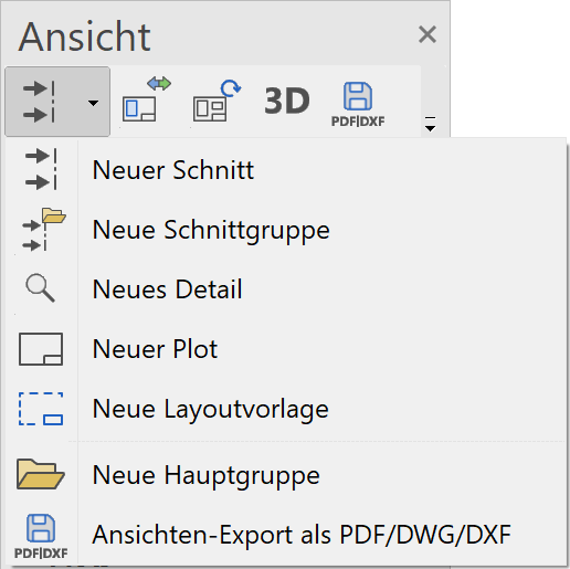
Create section
|
|
Views manager > New section |
| Insert menu > Section |
A new section is defined in the model. All relevant data should be assembled.
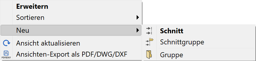
A new section can be generated using the corresponding header function or from the context menu of the views if a design model view is selected.
The desired settings have to be entered in the settings dialog window of the view. By clicking on  , the settings are saved and the view is created. The function MODIFY VIEW allows you to change the settings of the view after creation.
Tip
In ELITECAD Mechanics, a section view can be created directly in the plot view. After definition of the section line, the section view is placed in the plot view. The position of the section view is associated with the section line. When moving the origin view the section view is shifted as well. In order to stop this from happening, click the frame of the view and select CANCEL POSITION LINK from the context menu.
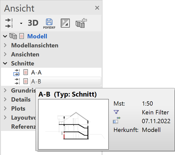
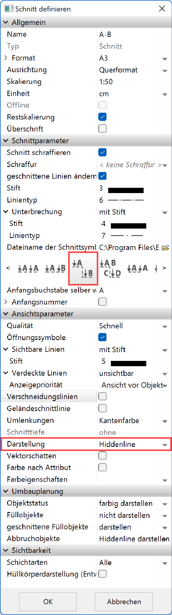
Section view parameters
General parameters
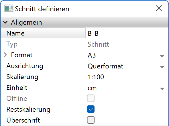
Name
The name is suggested automatically but can be modified. The program begins with the name "A-A" and continues with the name "B-B". If a name is used that already exists, a query appears asking the user whether the existing view is to be overwritten. It does not matter under which view type this is saved.
Type
Details in OUTPUT > VIEWS > GENERAL VIEW PARAMETERS.
Format
Details in OUTPUT > VIEWS > GENERAL VIEW PARAMETERS.
Orientation
Details in OUTPUT > VIEWS > GENERAL VIEW PARAMETERS.
Offline
Details in OUTPUT > VIEWS > GENERAL VIEW PARAMETERS.
Supplementary scaling
Details in OUTPUT > VIEWS > GENERAL VIEW PARAMETERS.
Heading
Details in OUTPUT > VIEWS > VIEWS.
Section parameters
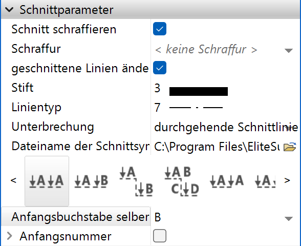
Section hatch
A section is hatched in ELITECAD Mechanics with the defined hatching parameters if the HATCH SECTION option is selected.
A section is hatched in ELITECAD Architecture according to the material definition of the individual, sectioned construction part so long as the HATCH SECTION option is selected. The associated hatching parameter therefore does not need to be set.
Modify section line
This option is only available in ELITECAD Architecture. The borders of the sectioned surfaces are normally drawn with the same pen that the construction part section has in the model. Selecting this option modifies these lines in the same way as the sectioned construction parts are displayed in the floor plan. Floors and girders are an exception. The pen from the material definition of these two objects is used here in accordance with the display depth.
Section line
A section line is generated automatically for each set pen and line type in section control.
A section arrow that was saved as a symbol is set at each end of this line. An example symbol sectionsymbol.d is saved here:
<ELITECAD installation path>\u\<version>\<ar\me>\glob\symbol
New symbols can also be created.
There are four different types of section lines:
- straight
- offset
- limited
- offset and limited
Users can choose between the same or a continuous designation for each type.
![]() Normal section / label A-A (entire model appears as a section)
Normal section / label A-A (entire model appears as a section)
![]() Normal section / label A-B (entire model appears as a section)
Normal section / label A-B (entire model appears as a section)
![]() Section stepped multiple times / label A-B
Section stepped multiple times / label A-B
![]() Section stepped multiple times / label A-B C-D
Section stepped multiple times / label A-B C-D
![]() Limited section / label A-A
Limited section / label A-A
![]() Limited section / label A-B
Limited section / label A-B
![]() Section limited and stepped multiple times / label A-B
Section limited and stepped multiple times / label A-B
![]() Section limited and stepped multiple times / label A-B C-D
Section limited and stepped multiple times / label A-B C-D
The letter for the section label can be freely selected.
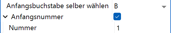
Optionally a number be used. This creates possibilities for cut labelling such as "A1-A1", "B2-B2" or "Z1-Z3". Alternatively, the letter can also be omitted so that the name consists only of digits, i.e. "1-1", "2-2" or "1-3" etc.
Height limit
Improved · 16 R1 · Improvements
With the limited section type, an upper and lower height limit can optionally be set.
Tip
In ELITECAD Architecture the section line is added to the active storey during section creation. The section line can be applied to other storeys using the function COPY INTO ACTIVE STOREY.
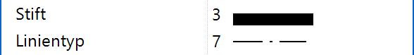
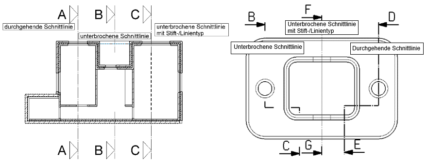
Modify section line parameters

If an existing section line is clicked on, separate parameters such as pen and line type can be modified in the property bar, or the shape may be changed using the handles.
![]() Broken section line:
Broken section line:
The section line is divided between the arrows.
![]() Continuous section line:
Removes the division described above.
Continuous section line:
Removes the division described above.
![]() Broken section line with pen/line type:
Broken section line with pen/line type:
The section line is divided between the arrows. The divided interval can be drawn with a user defined pen/line type. If this option is selected, the new parameters appear in the property bar.

View specific parameters
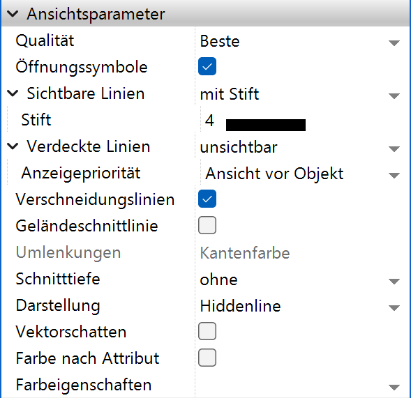
See chapter "Settings of a view" for a description of the general view parameters.
Terrain section line
If a terrain is visible in the section view this option activates the depiction of a section line of the corresponding original terrain (only possible if a reference terrain exists).

Redirections
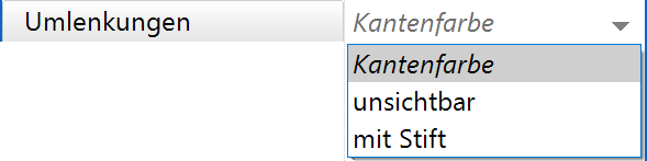
For stepped sections, the appearance can be defined at the redirections. With the option EDGE COLOUR the colour of the actual object in the 3D model is used. The option INVISIBLE draws the redirections with pen 0. A user defined appearance can be chosen with the option WITH PEN, where pen and line type can be selected.
Depth of section
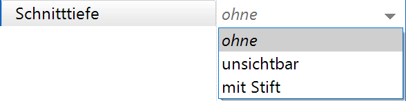
For normal and limited section views, a section depth can be defined. Depending on the selected option, objects that lie behind the entered depth are not displayed or displayed using a defined pen and line type. The depth distance is entered in the currently set units.
Depth of section - Without

If no depth is defined, all visible objects behind the section plane are displayed.


Depth of section - Invisible
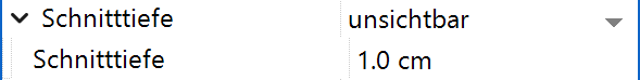
Objects lying behind the defined depth of the section plane are not displayed.


Section depth – With pen
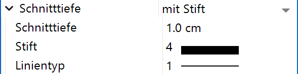
Objects, lying behind the defined depth of the section plane are displayed with the selected pen and line type.


Colour by attribute
Details in OUTPUT > VIEWS > GENERAL VIEW PARAMETERS.
Colour scheme 
Improved · 16 R1 · Improvements
Details in OUTPUT > VIEWS > GENERAL VIEW PARAMETERS.
Renovation planning (only in ELITECAD Architecture)
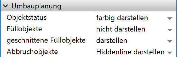
Object state
Details in OUTPUT > VIEWS > GENERAL VIEW PARAMETERS.
Fillings
Details in OUTPUT > VIEWS > GENERAL VIEW PARAMETERS.
Sectioned fillings
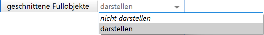
Sectioned fillings for walls and slabs are displayed in the view according to the setting of this option.
Demolition objects
Details in OUTPUT > VIEWS > GENERAL VIEW PARAMETERS.
Visibility (only in ELITECAD Architecture)
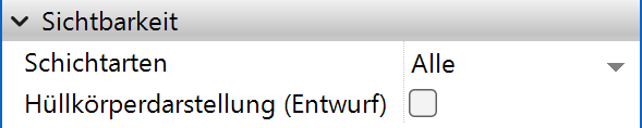
Layer types
Details in OUTPUT > VIEWS > GENERAL VIEW PARAMETERS.
Room hatches
Details in OUTPUT > VIEWS > GENERAL VIEW PARAMETERS.
Section group / elevation view
Improved · 16 R1 · Improvements
![]()
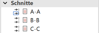
A section group is used to combine several sections that together describe an elevation view. The section group is created analogously to the main groups as a hierarchical element in the view management.
All section views that belong to an elevation view must be in the same section group and created with consecutive designations (e.g. A-B and C-D).
The section group can be placed as a unit in a plot view. Consecutive sections are automatically arranged next to each other and the position is automatically adjusted when changes are made.
Functions in the graphics window context menu
Define, modify or delete cut-out
Details in OUTPUT > VIEWS > FUNCTIONS IN VIEWS.
Workshop
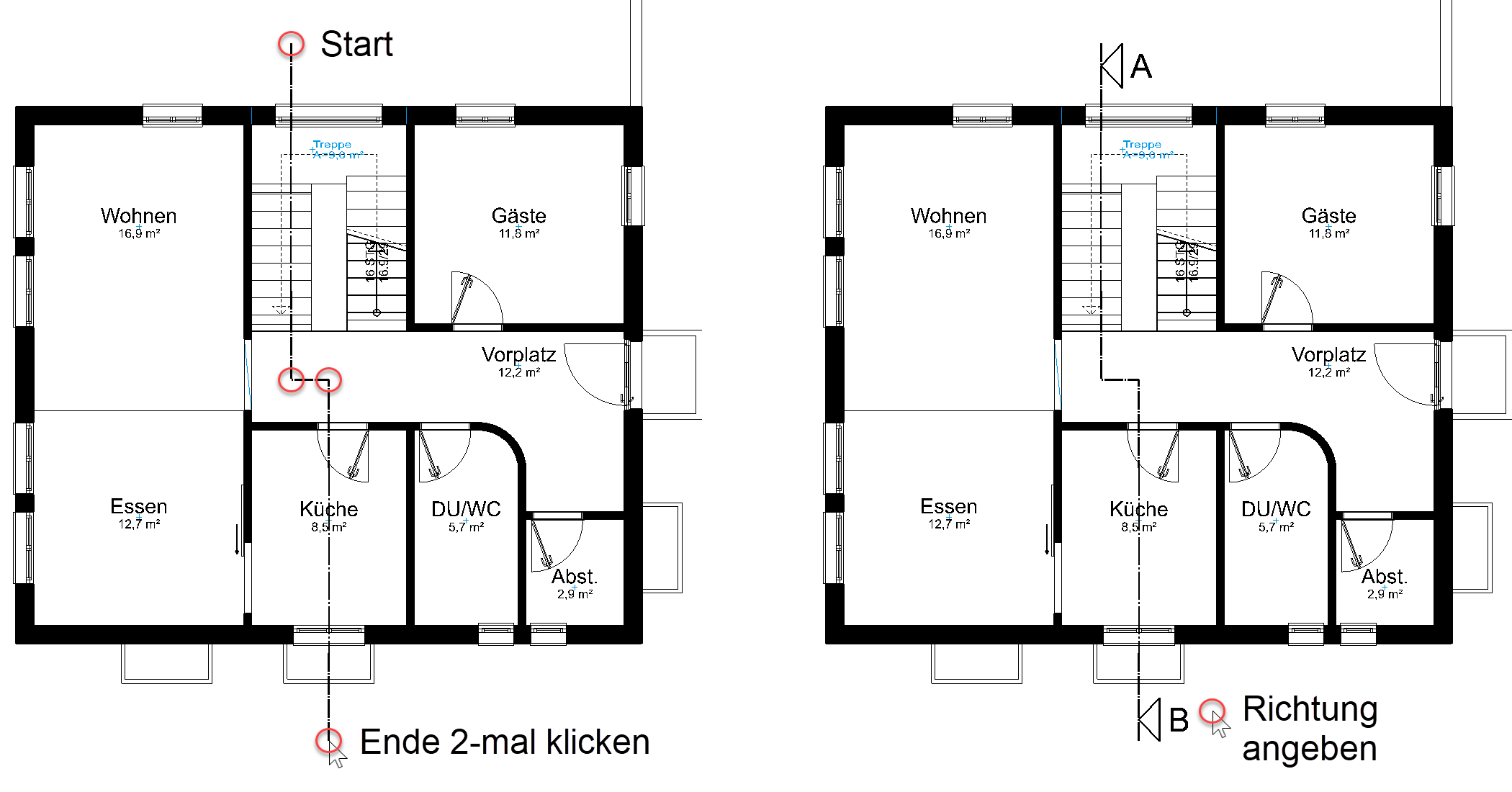
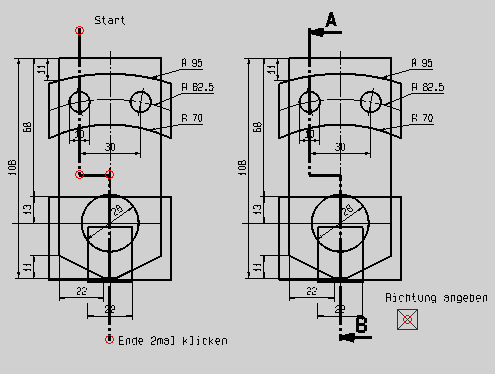
Generate sections
Ideally, a new section is defined from the model. All relevant design model data must be assembled.
Click on the function CREATE NEW SECTION
![]()
or right-click on the title "Sections" in views manager.
Set section dialog window with stepped section line.
Enter point 1 for section gradient [identical point > end]
Enter one point of the section line after the other. Click a second time on the last point to close.
Which direction?
The viewing direction of the section can be defined depending on the side you move the cursor to. This can be easily controlled using the alternating arrow symbols.
Note
Avoid placing the section exactly on the gable of a gabled roof, but rather a bit off to one side.
Once the direction is set, the section is calculated.
In ELITECAD Mechanics all sectioned construction parts are automatically hatched.
In ELITECAD Architecture, all opened door leaves are temporarily hidden during section control so that they are not visible in the section. All sections of the construction parts are hatched in accordance with their material definition.
The section has now been added to the views manager and can be selected.