Switches
VR on/off
|
|
Image properties |
After activating the function, the output of the current camera image is enabled in the VR glasses. At the same time the image is displayed in the graphics window according to the setting in the dialog Input devices > VR.
To be able to use the VR glasses, the drivers have to be installed appropriately.
Clipping on/off
|
|
View toolbar |
| Image properties | |
| Ctrl + I |

This function is used to trim the 3D-image area temporarily. This gives you a better overview during 3D-editing.
Once clipping has been selected, the clipping property bar is displayed. The active work plane is used as the clipping plane.
Clipping on/off
![]()
This switch turns Clipping on and off.
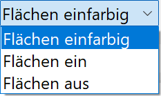
Section surface
 Section surface mono coloured
 Section surface on
 Section surface off
This setting defines if the section surface should be displayed or not. Either the depiction is done with the colour of the object or mono coloured. The section surface is only displayed if just the upper clipping plane is active.
Upper and lower clipping plane

Upper and lower clipping planes can be switched on and off independently. The value fields define the distance to the current working plane.
Clipping parameter
![]()
The parameter button opens the clipping dialog window.
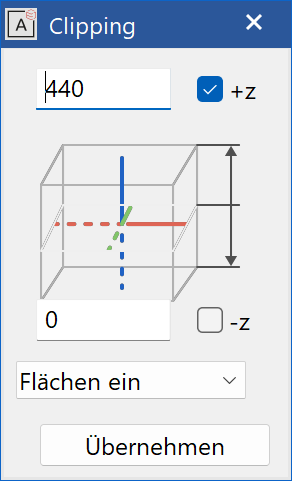
For "z", you can enter the distance from the work plane in a positive or negative Z-direction. If you do not enter a value for the Z-distance, the default value is 0. When you click  , the specified Z-values are applied and the image is refreshed.
If only the positive range is clipped, there are three different options for displaying the section plane.
Change clipping
Changing the values in the property bar or in the parameter dialog window moves the clipping plane. Alternatively, the clipping plane is moved in parallel direction using the handles.
The orientation of the clipping plane is modified by changing the work plane.
Workshop
Clipping applies to the current image and work plane.
Set the following switches in the property bar:

Now you can move the clipping plane through the model using the handles.
| Architecture | Mechanics |
|---|---|
 |
 |
Grid on/off
|
|
Switches toolbar |
| Image properties |
This check box controls the depiction of a grid on the screen.
Depending on whether the check box is selected, the grid is either displayed or hidden.
You can define the grid settings under the SETTINGS menu > OPTIONS > DEPICTION > TOOLS.
Texts on/off
|
|
Switches toolbar |
| Image properties |
This check box controls the depiction of texts on the screen.
Depending on whether the check box is selected, the texts are either displayed or hidden.
Arrows on/off
|
|
Switches toolbar |
| Image properties |
This check box controls the depiction of arrows on the screen.
Depending on whether the check box is selected, the arrows are either displayed or hidden.
Dimensions on/off
|
|
Switches toolbar |
| Image properties |
This check box controls the depiction of dimensions on the screen.
Depending on whether the check box is selected, the dimensions are either displayed or hidden.
Hatches on/off
|
|
Switches toolbar |
| Image properties |
This check box controls the depiction of hatches on the screen.
Depending on whether the check box is selected, the hatches are either displayed or hidden.
Perspective on/off
|
|
Switches toolbar |
| View menu > Switches > Perspective | |
| Ctrl + Shift + P |
This check box controls the depiction of perspective. When you switch on perspective, differences in rendered size aim to create an illusion of depth.
Line types (single) on/off
|
|
Switches toolbar |
| View menu > Line types... |
Your entry defines whether specific line types are taken into account for the output (screen, printer) or for manipulation operations (such as "Delete block/section").
If the check box is selected, specific line types can be selected by entering their line type numbers. All other line types are hidden but are not lost. By entering "-1" as the line type number, you can reactivate all line types.
If you prefix the line type number with a "^", it excludes the designated line type, e.g. "^2" means all line types should be displayed except for line type 2.
Pens (single) on/off
|
|
Switches toolbar |
| View menu > Pens... |
Your entry defines whether specific pens are taken into account for the output (screen, printer) or for manipulation operations (such as "Delete block/section").
If the check box is selected, specific pens can be selected by entering their pen numbers. All other pens are hidden but are not lost. By entering "-1" as the pen number, you can reactivate all pens.
If you prefix the pen number with a "^", it excludes the designated pen, e.g. "^2" means all pens should be displayed except for pen 2.
See also Pen filter for elements only.
Light on/off
|
|
Switches toolbar |
| View menu > Switches > Light... | |
| Ctrl + L |
This check box controls how light sources are taken into account for the colour depiction in the solid model. Key combination Ctrl + L .