Work plane
Reset work plane
|
|
Create New toolbar |
| Draw menu > Work plane > Reset work plane | |
| Image properties |
This function is used to place the edit plane back into the original floor plan plane of the current storey.
Work plane on surface
|
|
Create New toolbar |
| Draw menu > Work plane > Work plane on surface | |
| Image properties |
Use this function if you want to place a new edit plane precisely on top of an existing surface.
After you activate the function, you must click the desired plane in 3D.
Tip
Curved surfaces can also be selected. The Edit plane is then placed tangential to the plan.
Work plane over 3 points
|
|
Create New toolbar |
| Draw menu > Work plane > Work plane by 3 points | |
| Image properties |
Use this function if you want to place a new edit plane to pass precisely through 3 specific points in the room.
You need to enter 3 points for which the entry row or 3D capture function can be used. The first point defines the origin, the second point the direction of the X-axis and the third point determines the XY-level.
Examples of point entries:
With an entry line:
- X50,Y-100,Z50
- X50,Y100
- ,,50
- a45,d100,Z50 etc.
With 3D point capture mode:
- Any points of a Box, etc.
Select work plane origin
|
|
Create New toolbar |
| Draw menu > Work plane > Select work plane origin | |
| Image properties |
This function is used to place the origin of the coordinate system on the desired point.
Given a point entry, the work plane undergoes a geometrical translation that places the origin of the coordinate system at the specified point.
Create work plane using perpendicular
|
|
Create New toolbar |
| Draw menu > Work plane > Create work plane using perpendicular | |
| Image properties |
Use this function if you want to place a new edit plane to connect two points normally.
The first point defines the position of the origin of the axes of coordinates of the new edit plane. The second point defines the direction of the Z-axis by taking the connection between the first and second points as a normal vector for the edit plane.
Tip
In this process, the direction of the X-axis is set to be horizontal.
Change work plane
|
|
Create New toolbar |
| Draw menu > Work plane > Change work plane | |
| Image properties |
In a separate window, the work plane can be rotated around one of the axes or moved.
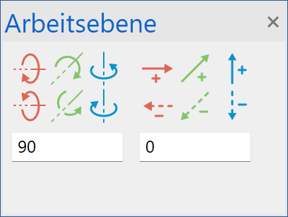
This window is a docking menu and behaves in the same way as the layer, storey and views windows.
Camera pivot point
|
|
View toolbar |
| Image properties |
This function is used to realign the camera pivot point.
Normally, the camera pivot point is the centre of the screen. If you want to rotate objects that are far from the zero point, it is better to reset the centre point for the rotation to enable precise navigation. You can do this by clicking the object in question (which selects the centre point of the surrounding rectangle) or via point entry.
Tip
The pivot centre point is reset every time the image section is modified.
Define coordinate system
|
|
Settings toolbar |
| Image properties |
The coordinate system can be rotated via an angle or point entry. All inputs and manipulations (e.g. vertical or horizontal) will then refer to the new coordinate system.
The new entry generates a symbol on the screen. Double-clicking a coordinate symbol switches to that coordinate system. Double-clicking the main coordinate symbol in the lower left corner switches back to the original work plane.
If custom coordinate systems have been saved with the drawing, they are automatically displayed when it is loaded.
| Origin | Coordinate system rotated |
|---|---|
 |
 |
Tip
A coordinate symbol can be selected and deleted.
View position
|
|
Image properties |
This function is used to view the 3D-object from any point in any direction. You can finely tune the direction of view via the subsequent Camera dialog window. The design model depiction is automatically set to be in perspective.
After you activate the function, you will be prompted for:
- The digitisation of the view position by entering a value or capture mode
- The height of the view position (Z-value compared to the active work plane)
- The digitisation of the focal point by entering a value or capture mode
- The height of view point (Z-value compared to the active work plane)
Now the 3D-image is rendered according to the configured parameters and displayed in the 4-view window.