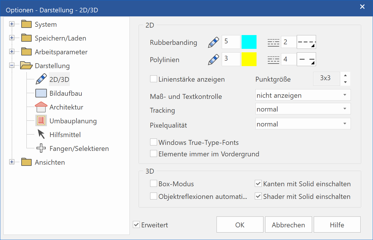
Depiction
2D/3D
Extended settings
Only visible if selected.
2D – Rubberbanding
This is where you specify the pen and line type for rubberbanding (an elastic band attached to the cursor).
2D - Polylines
This is where you specify pen and line types for displaying lines (e.g. for selection with block/section functions).
2D - Show line width
On screen, the line width is displayed according to the width for each pen in the colour settings.
2D - Point size
The point size in pixels is used for the display of point clouds.
2D - Dimension and text checks
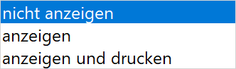
In order to determine whether linear dimensions no longer possess any association, this can be displayed optically. The depiction uses red arrows and highlights the dimension text in red. A red arrow means that the point at which the dimension was set has lost its association and no longer matches the depicted size.

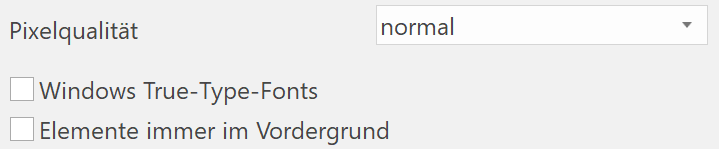
2D - Image resolution
![]()
This function is used to convert monochrome bitmaps into greyscale.
Once you switch to high quality, all monochrome bitmaps are displayed in greyscale. Likewise, upon switching to normal quality, they are displayed in monochrome.
Tip
For colour images, the IMAGE RESOLUTION function does not have an effect, as colour images are always displayed in high quality. If there are both monochrome and colour images on the screen, the monochrome images are not converted either.
2D - Tracking
![]()
When placing objects, the selection to be placed is attached to the cursor. The option simple displays only the 2D rectangle or the 3D box.
2D - Windows True-Type-Fonts
(Extended setting)
TTF ELITECAD texts are selected and depicted with real Windows True Type Fonts. Otherwise, there is an approximate depiction.
2D – Elements always in foreground
(Extended setting)
If the option is inactive (default setting), the individual object's visibility is controlled by the sort order.
If this option is selected, elements, texts, line hatches, dimensions and arrows are always drawn before the infill hatch no matter the sequence of the objects.
Explanation
As the control of foreground/background was not available in versions before V11, this option is set automatically if you load plans from versions predating V11 in order to prevent the plan image from changing. If a new drawing is loaded, the check box is automatically reset.
3D - Box mode
Using the "3D – Box mode" check box, you can depict a box outlining a part instead of its exact 3D depiction. This drastically accelerates image assembly. The only objects displayed as a 3D-encasing box are those that are predefined by selecting them and pressing Ctrl + num * . You can remove this depiction type from the current selection by pressing Ctrl + num / .
3D – Automatic object reflections
When the shader technology is switched on and the option is active, the object reflections are automatically calculated or updated.
3D – Activate edges with solid mode
If you switch to solid mode, the edges are automatically activated.
3D – Activate shader with solid mode
If you switch to solid mode, the shader technology is automatically activated.
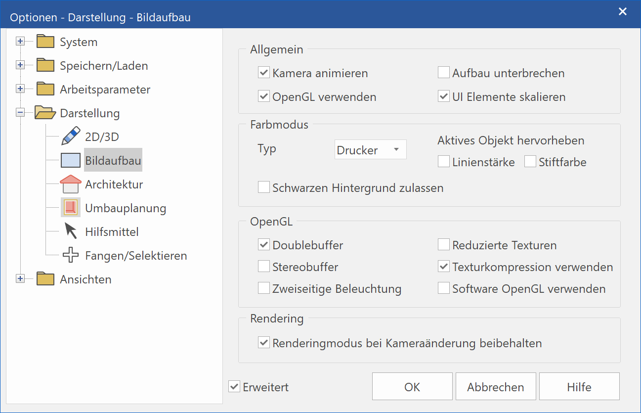
Image display
Extended settings
Only visible if selected.

General – Animate camera
If you move the rotated design model back to its starting position using the IMAGE START POINT function, the camera is shifted gradually, not jerkily.
General - Interrupt display
The "Interrupt display" parameter cancels the image assembly as soon as a new image assembly becomes necessary due to a modification (zoom, move, change window size, etc.). This speeds up the system, as that way an individual image assembly is not carried out completely before being overwritten anyway.
General - Use OpenGL
On by default. If this check box is deselected, the GDI graphic display is always used except in solid mode.
General - Scale UI elements
New · 16 R1 · Improvements
When this check box is inactive, user-interface elements such as the frame, axes, crosshairs, marker, etc... are depicted with lines that are one pixel wide(actual size of a pixel varies based on screen resolution).
When it is active, these elements are scaled according to the scaling factor set for your monitor found in the display settings. This can help with visibility of UI elements especially when working with monitors with very high resolutions.
General - Pen filter for elements only
When this check box is selected, the pen filter (View > Pens...) only applies to elements, but NOT to dimensions, hatches or arrows.
The selected pen filter is only used for the image view but not for manipulation functions.
Colour mode - Type
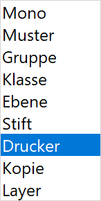
Default colour mode setting for ELITECAD start or in New file.
Details in Colour mode
For "Printer" colour mode, the option ALLOW BLACK BACKGROUND also appears. For the "Model, Group, Class, Layer" colour modes, the colours can be specified.
Colour mode - Highlight active object by
The active (current) object/model can be highlighted in two different ways in order to make it more distinguishable from others.
It is displayed brighter (thicker) than all others.
It is depicted with the pen colour in the colour mode "Mono". In other colour modes, this option does not contrast very well.
Colour mode – Allow black background
When switching the background colour, switching to black is prevented, in case also lines are displayed in black. If this option is active, then this combination is possible.
OpenGL - Double buffer
The "Double buffer" check box only takes effect in combination with OpenGL. This is normally always switched on and enables smooth, dynamic rotation in 3D without jerky movements.
OpenGL – Stereo buffer
The stereo buffer has to be activated for the display on stereoscopic hardware in order to create a 3D effect.
OpenGL - Two-sided lighting
Off by default. In this state, ELITECAD takes over rendering of lighting.
OpenGL – Reduced textures
Texture images with large amounts of data can be displayed in OpenGL with reduced quality in order to save memory and rendering time.
This option controls whether or not high-resolution textures are to be used.
OpenGL – Texture compression
Texture compression is a procedure for reducing the storage need of textures. This also carries a benefit in terms of speed.
OpenGL – Use OpenGL Software
(Extended setting)
In rare cases, if there is an error when rendering with the graphic/video card, it may be necessary to select this check box. Then ELITECAD takes over rendering images. However, this leads to worse performance.
Render – Update render mode in case of camera change
If this option is selected, rendering is automatically restarted after each change to the camera (zoom, rotate). When it is deselected, the design model is restored to the solid depiction and rendering must be re-triggered manually.
Architecture
This option is only available in ELITECAD Architecture.
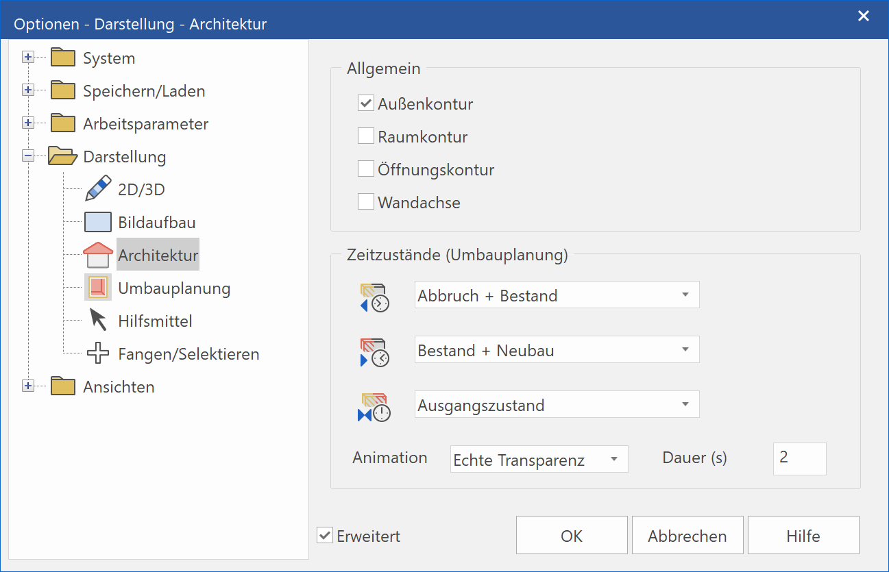
General - Outer contour
Show or hide perimeters.
General - Room contour
Show or hide room contours.
General - Opening contour
When the opening contour is selected, the floor plans of window openings, doors and wall openings are displayed as graphical aids.
General - Wall axis
Show or hide wall axis. Switching on wall axes helps connect two walls. The axis is depicted in blue pen.
Time states (renovation planning) – Visibility filters
Three time states are configurable: Before or after the renovation, as well as a working state. Switching is possible via functions in the RENOVATION PLANNING toolbar.
Time states (renovation planning) – Animation
The change between two time states can be animated with simple and good transparency quality. The duration of the animation is set in seconds.
Renovation Planning
This option is only available in ELITECAD Architecture.
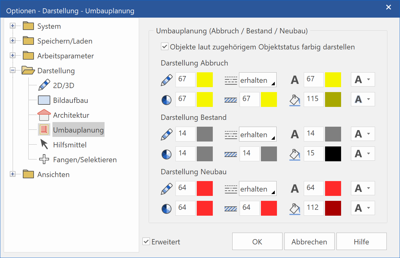
Object colouring

Objects are depicted either coloured with the defined depiction parameters of the states or according to the material settings of the representation levels.
For each of the states: demolition, existing and new construction, the same colours, line type settings and text options are available.
Colour settings
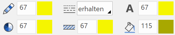
You can select the colour for lines, 3D surfaces, texts, line hatches and filling hatches.
The line type either remains the same or is overwritten.
Text settings


Texts may remain unchanged or are underlined, crossed out or over lined.

The background of texts may remain unchanged or is depicted with a fill colour or inverted. It may also be depicted with a borderline or inverted with borderline.
Tools
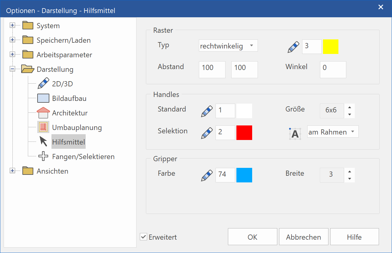
Grid - Type
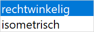
This function specifies the grid type.
Grid - Pen
Pen colour of grid
Grid - Distance
The first value matches the point distance of the grid in the X-direction. The second value matches the point distance of the grid in the Y-direction in terms of the configured units.
Grid - Angle
The value specifies the desired angle of the grid.
Handles - Standard

Pen colour of handles
Handles - Size
The size of the handles can be configured from 3x3 pixels up to 10x10.
Handles - Selection

Pen colour of a selected handle
Handles –Text
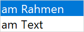
Specify the position of text handles here. If the option is set to "on frame", the handles have a specific distance from the text. For the ON TEXT option, the handles are directly on the text.
Gripper - Colour
Pen colour of grippers
Gripper - Width
The width of the grippers can be configured from 1pixel up to 5 pixels.
Snap/Select
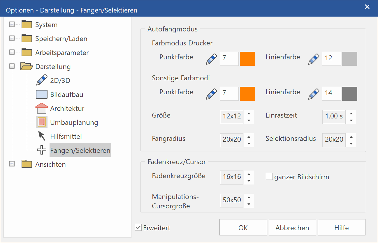
Auto snap mode - Point colour
Specify the pen colour of temporary capture points
Auto snap mode - Size
The size of the temporary capture points can be configured to be from 10x10 up to 20x20 pixels.
Auto snap mode - Line colour
Pen colour of temporary help lines
Auto snap mode – Snap time
If you hover over a point with the cursor, it takes the length of time specified here until the temporary capture point is shown.
Auto snap mode – Snap radius
The snap radius is the distance (in pixels) from the cursor within which the closest point is searched in the graphics window.
Auto snap mode – Selection radius
The selection radius is the distance (in pixels) from the cursor within which the closest object is searched when clicking in the graphics window.
Crosshair/Cursor – Crosshair/Cursor
The size of the crosshair is available is several options.
Crosshair/Cursor – Crosshair size – full screen
This option overrules the size selection and draw the crosshair over the whole graphics window.
Crosshair/Cursor – Manipulation cursor size
While moving / copying objects the manipulation cursor is displayed. Its size can be selected from several options.