Work Parameters
General
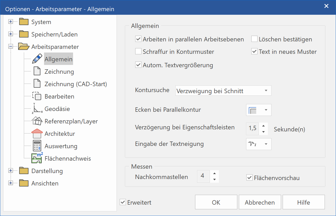
General – Work in parallel work planes
When this option is selected, it not only takes into account elements on the current work plane (as would be the case when the option is switched off), but also elements located on work planes that are on a different height parallel to the active work plane. In the default state, capture points are found on all storeys in ELITECAD Architecture.
General – Confirm delete
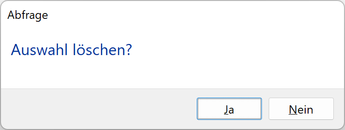
When this option is selected, after you attempt to delete, a dialog window opens asking you to confirm the deletion.
General - Hatch in contour model
This setting is only meaningful if you are working in the "V11 user interface".
The hatch is assigned to the model of the hatched contour. If the contour consists of multiple patterns, the hatch is assigned to the one pattern that shares the largest part.
General – Text into new model
This setting is only meaningful if you are working in the "V11 user interface".
The text is assigned to a new model.
General – Automatic text enlargement
Small texts are displayed enlarged during entry or when editing.
General - Contour search
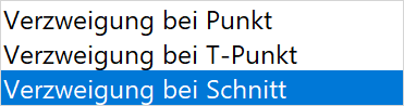
Here you can specify branching mode for contour search (Measure area, Hatch).
You can use this function to specify the automatic process for a drawn contour.
Branching at point
The crosshair moves onto where the start/end points of two lines meet.
Branching at T-junction
If the start/end point of line is on another line, the crosshair continues at this branching point.
Branching at section
If two lines cross, the crosshair continues onto the other line.
Tip
Contour search is used for the following functions: HATCH, AUTO-HATCH, PLANES, EXTENT, PLANE FOCAL POINT AND PARALLEL CONTOUR.
General - Corner with parallel contour
The option specifies how corners are treated when generating a parallel contour.
![]() No other elements are added.
No other elements are added.
![]() Corners are added matching the existing contour.
Corners are added matching the existing contour.
![]() The corners are treated as curves whose radius corresponds to the distance of the parallel contour.
The corners are treated as curves whose radius corresponds to the distance of the parallel contour.
Delay with property bars
If an entry is changed in the property bar, the length of time specified here is how long it takes until the value is adopted.
If the "tilde character" (~) is selected, the change must be confirmed by pressing --enter++ .
Entry of text slant
Determines how the angle is measured for the text slant.
![]() Calculated from the vertical axis (0°)
Calculated from the vertical axis (0°)
![]() Calculated from the horizontal axis (90°)
Calculated from the horizontal axis (90°)
This entry is only available for CAD character sets, not for TTF fonts.
Measure – Decimal places when measuring
The output of decimal places is rounded to the specified value. Applies only to outputs. Internally, renderings use all available decimal places.
Measure – Preview area
If the MEASURE AREA function is selected, the contour in focus is highlighted.
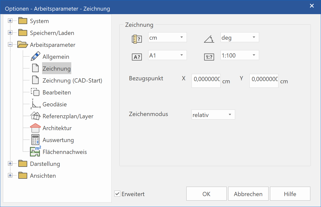
Drawing
Extended settings
Only visible if selected.
Drawing parameters of active drawing
This tab displays the parameters of the active loaded drawing. If no drawing is loaded or the drawing has no saved parameters, the parameters saved in NEW DRAWINGare displayed.
Drawing - Unit

Drawing - Angle unit

Drawing - Format

Drawing - Dimension

Drawing - Reference point
The X and Y values list how far the reference point is in centimetres from the start or, after NEW FILE, from the centre of the screen. This is also the absolute zero point (X=0, Y=0).
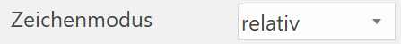
Drawing - Draw mode
(Extended setting)
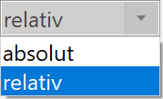
The default setting is RELATIVE. With this setting, enter all figures for a point request in the entry line relative to the current CAD cursor position.
With the ABSOLUTE setting, the figures you enter are always calculated based on the CAD reference point. This is normally in the centre of the screen in CAD.
Tip
You can click on the symbol adjacent to the value in the value field to switch between "relative" and "absolute".

![]() Characters for absolute
Characters for absolute
![]() Characters for relative
Characters for relative
Drawing (CAD start)
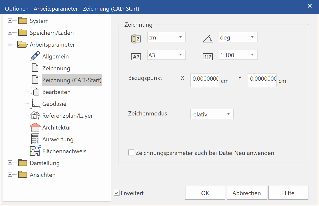
This tab displays the presettings. These settings take effect right after ELITECAD is launched and optionally after NEW FILE.
The parameters are the same as those described under DRAWING.
Edit
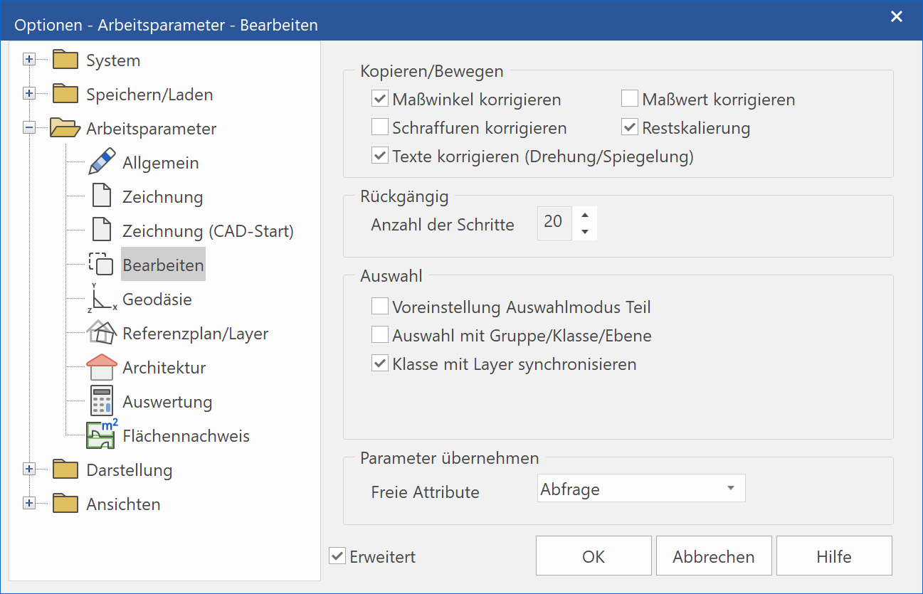
Copy/move - Correct dimension angle
If this parameter is set, dimension texts are adjusted with the rotation so they are not upside-down.
Copy/move - Correct dimension value
If this parameter is set, dimension texts (single dimensions) are automatically adjusted after manipulations (move, copy, rotate, scale, etc.). The architecture dimension (chain dimension) is always adjusted automatically.
Tip
Be careful with modified dimension texts:
If dimension texts were modified, they are corrected back to the true value after manipulations.
Copy/move - Correct hatches
If this parameter is set, hatches are rotated during manipulations.
Copy/move - supplement scaling
With functions that use scaling, when SUPPLEMENT SCALING is selected, the "rest" items are scaled (text, dimensions, arrows and hatches).
Copy/move - Correct texts (Rotation/mirroring)
If this parameter is set, texts are adjusted with the rotation so they are not upside-down. In keeping with the standard, the check box must be selected so that texts are always displayed in a readable manner.
Undo – No. of steps
Can be configured between 0 and 100 %. As increasing the number of steps also increases the number of saved operations; this number also has an effect on performance depending on the hardware.
Selection - Selection using Group/Class/Level
If this check box is ticked, you can work with the full organisational scheme. If the drawing is structured using layers, the option should not be selected.
Tip
We recommend not changing the presets in ELITECAD Architecture.
When this is selected, the organisational structure of the active model is displayed in the status bar on the bottom right
(M: G: C: L: )

The "Selection" toolbar displays the ACTIVATE MODEL and NEW MODEL functions and the selection mode for model, group, class and layer.

Selection – Synchronise class with layer(s)
This function is important for carrying over plans from version 9.2 or earlier.
When this option is selected, the classes are linked with the layer. The layers have the same names as the classes. The option should be selected if you are working with plans from version 9 and higher and have used the plan filter.
Selection - Presetting for part selection mode
When it is selected, the "Selection mode for part" is selected, if the "V11 user interface" is activated.
Selection - Only apply attributes to chosen model
This setting is only available in ELITECAD Mechanics.
The option “Assign attributes on selected model only” controls, how attributes are applied to the active model and its copies via the attribute dialog. If the option is not activated the attributes are assigned to all models with the same attribute number.
Geodesy
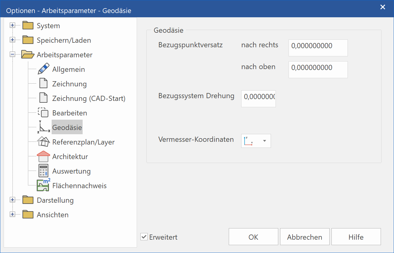
Geodesy - Reference point alignment - right
The value you enter here is taken into account in the COORDINATES OF POINT function and all specified coordinates.
Geodesy - Reference point alignment - upwards
The value you enter here is taken into account in the COORDINATES OF POINT function and all specified coordinates.
Geodesy - Rotate reference system
The value you enter here in degrees is taken into account in the COORDINATES OF POINT function and all specified coordinates.
Geodesy - Dimensioning coordinates

Y: upwards, X: to the right
The first coordinate for entry and output is the X-value, and then comes the Y-value.
Positive values for X go upwards and for Y go to the right
The first coordinate for entry and output is the Y-value, and then comes the X-value.
X: downwards, Y: to the right
The first coordinate for entry and output is the Y-value, and then comes the X-value.
Here, the positive x-axis points downward.
Reference plan/layer
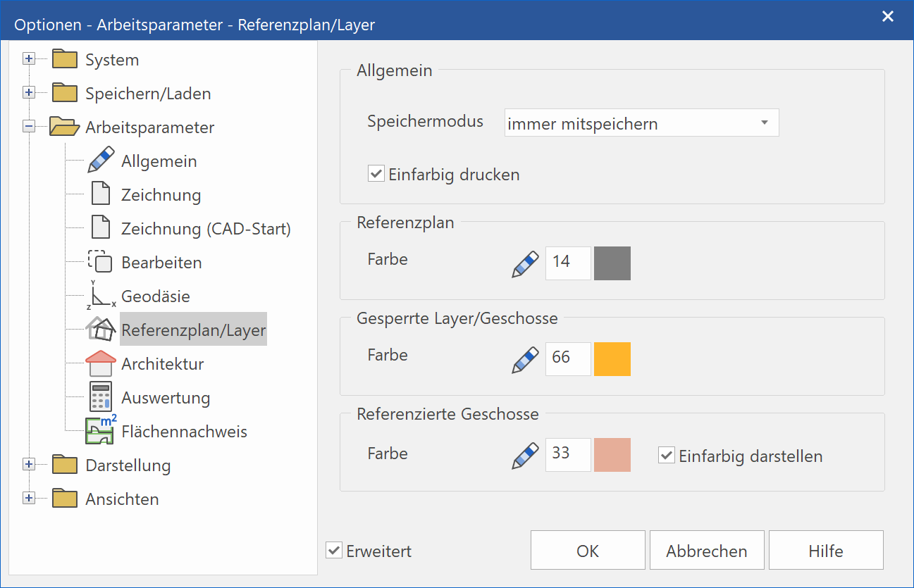
Save mode
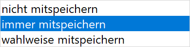
Behaviour of reference plan when saving
With "selection for inclusion in save", a query appears.
Print in single colour
Behaviour of reference plan when printing
Colour of reference plan

Specifying pen colour for reference plan
Colour of blocked layer/storey
Specifies the pen colour of the locked layer and locked storeys (only in ELITECAD Architecture)
Colour of referenced storey
Specifies the pen colour of the referenced storeys (only in ELITECAD Architecture)
Using a single colour is an optional setting.
Architecture
This option is only available in ELITECAD Architecture.
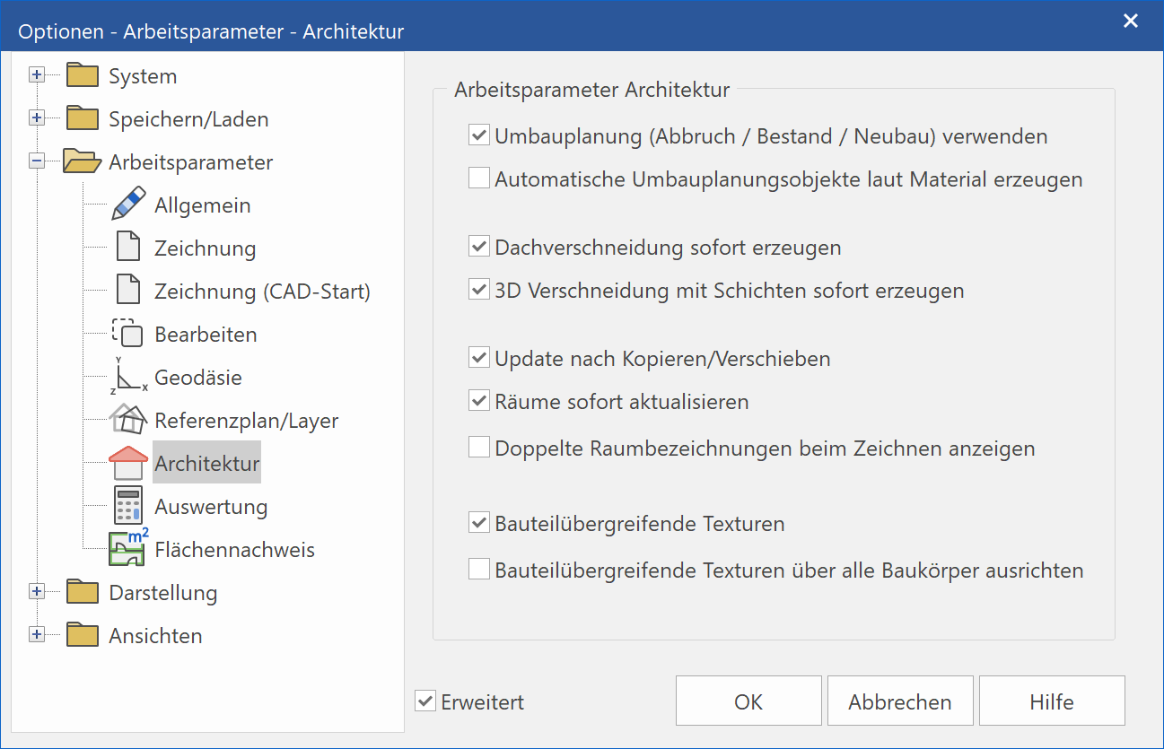
Extended settings
Only visible if selected.
Architecture work parameters – Use renovation planning
This setting is the main switch to activate renovation planning. Only if this option is active, can the objects be assigned to a renovation planning state and the assembly filter for the states be used.
Architecture work parameters – Renovation planning objects according material
Some renovation planning objects are created automatically (e.g. filling walls for demolished windows). You can select the depiction mode for these new objects, which is done either coloured using the defined depiction parameters of the states or according to the material settings of the representation levels.
Architecture work parameters - Generate roof sections immediately
Deselecting this reduces the processing needed and increases performance. This can be refreshed later using the REFRESH AR-OBJECTS menu item.
Architecture work parameters – Create 3D intersection with layers immediately
Deselecting this reduces the processing needed and increases performance. This can be refreshed later using the REFRESH AR-OBJECTS menu item.
Architecture work parameters - Refresh after move/copy
Deselecting this reduces the processing needed and increases performance. This can be refreshed later using the REFRESH AR-OBJECTS menu item.
Architecture work parameters – Refresh rooms now
If this option is deactivated, the rooms are not automatically adjusted if the walls around the rooms change. You can refresh this later via the menu item LAY-OUT > REFRESH ROOMS.
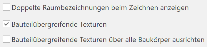
Architecture work parameters – Show duplicated room descriptions while drawing
This option helps the person drawing avoid creating room contours that are no longer closed when performing manipulations in the floor plan.
Architecture work parameters – Textures across construction parts
If this option is selected, all construction parts are given the same texture so that no textural transition is visible between storeys or at the meeting points of walls.
Tip
This option restricts texture alignment to single buildings.
Architecture work parameters – Align textures across construction parts over all structures
This option restricts texture alignment to single buildings.
Quantities
This option is only available in ELITECAD Architecture.
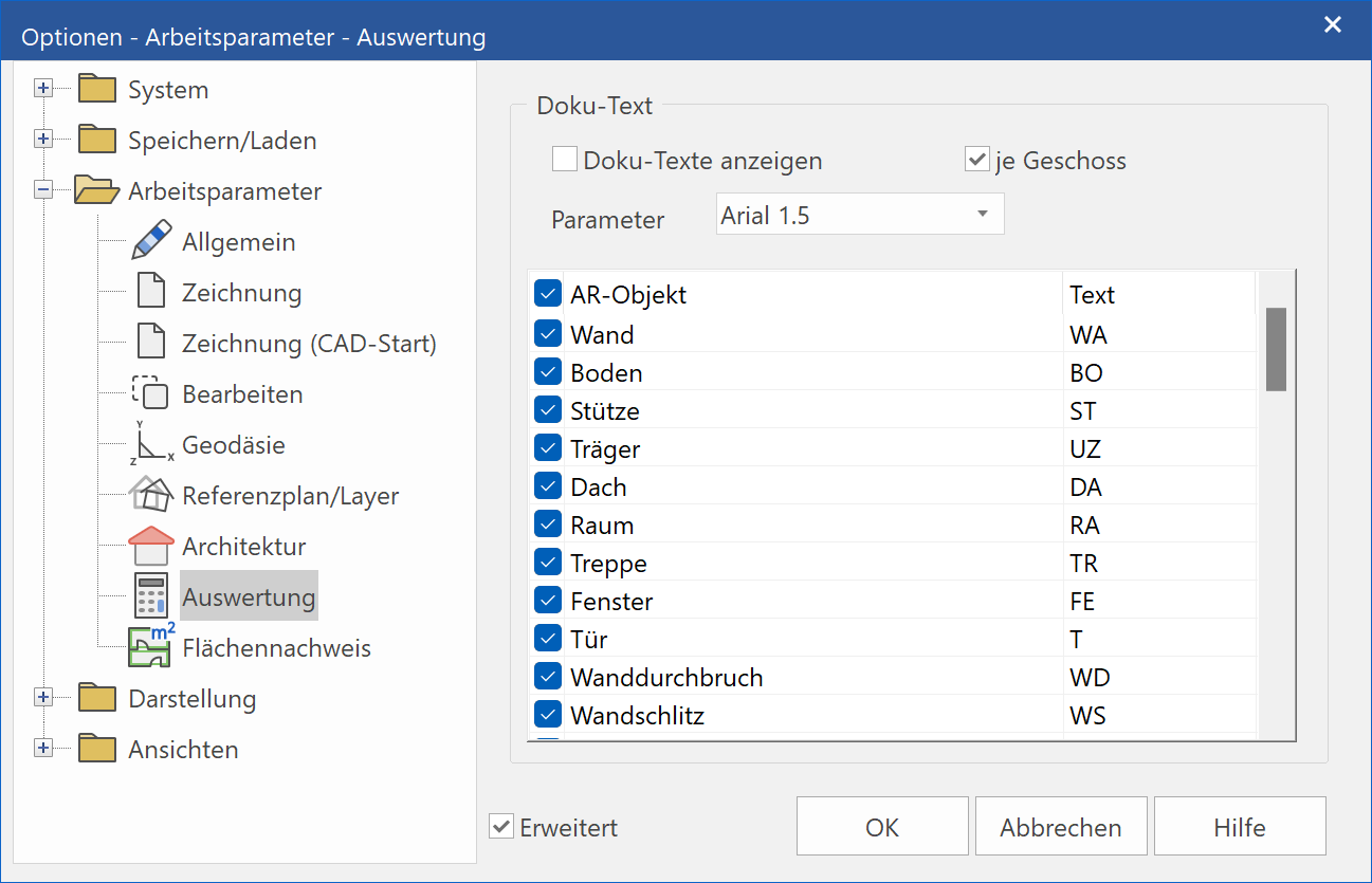
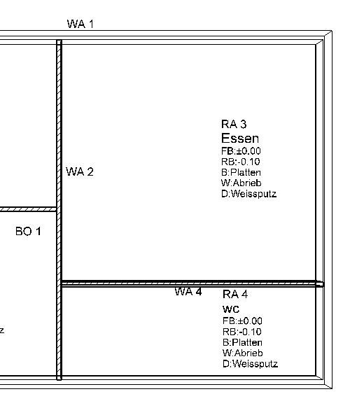
Quantities – Display docu-text
When this is selected, an additional text is written into the plan for all architecture objects following the SUMMARY TO PROJECT BOOK function. The name consists of an architecture object abbreviation and a serial number.
For example, WA1, etc. Wall Number 1, RM1, etc. Room Number 1, etc.
General – By storey
The assignment of docu-texts can be defined for each storey.
General – Parameters
Text parameters for the docu-text.
General – AR-object | Text
This table can be used to define the assignment of abbreviations to architecture objects. You can enter the abbreviations in the text fields.
Area verification
This option is only available in ELITECAD Architecture.
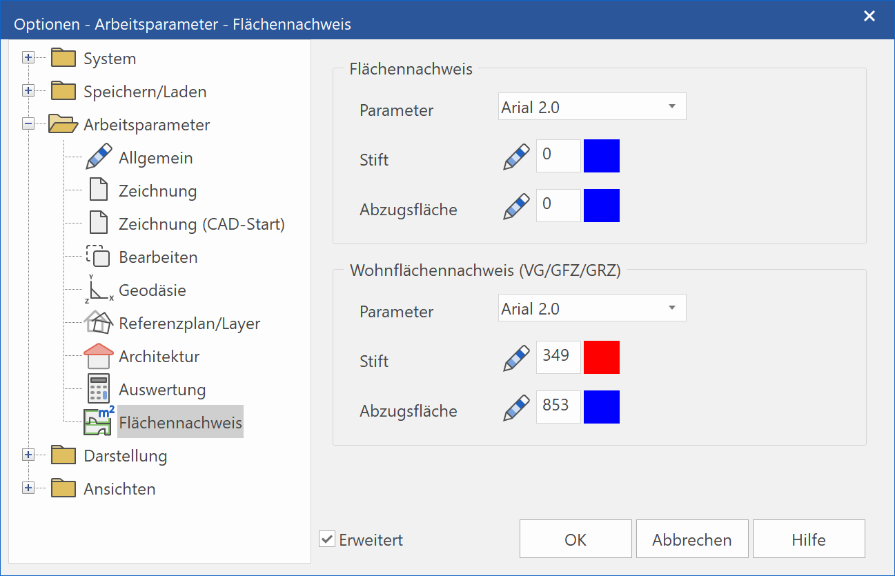
Area verification
Settings parameter for the area verification that is generated using the AREA VERIFICATION function in the EXTRAS menu > QUANTITIES.
Living space verification
Settings parameter for the living space verification that is generated using the functions - LIVING SPACE VERIFICATION - FULL STOREY VERIFICATION - FLOOR AREA RATIO VERIFICATION - BUILDING COVERAGE RATIO VERIFICATION in the EXTRAS menu > QUANTITIES.
Mechanics
These options are only available in ELITECAD Mechanics.
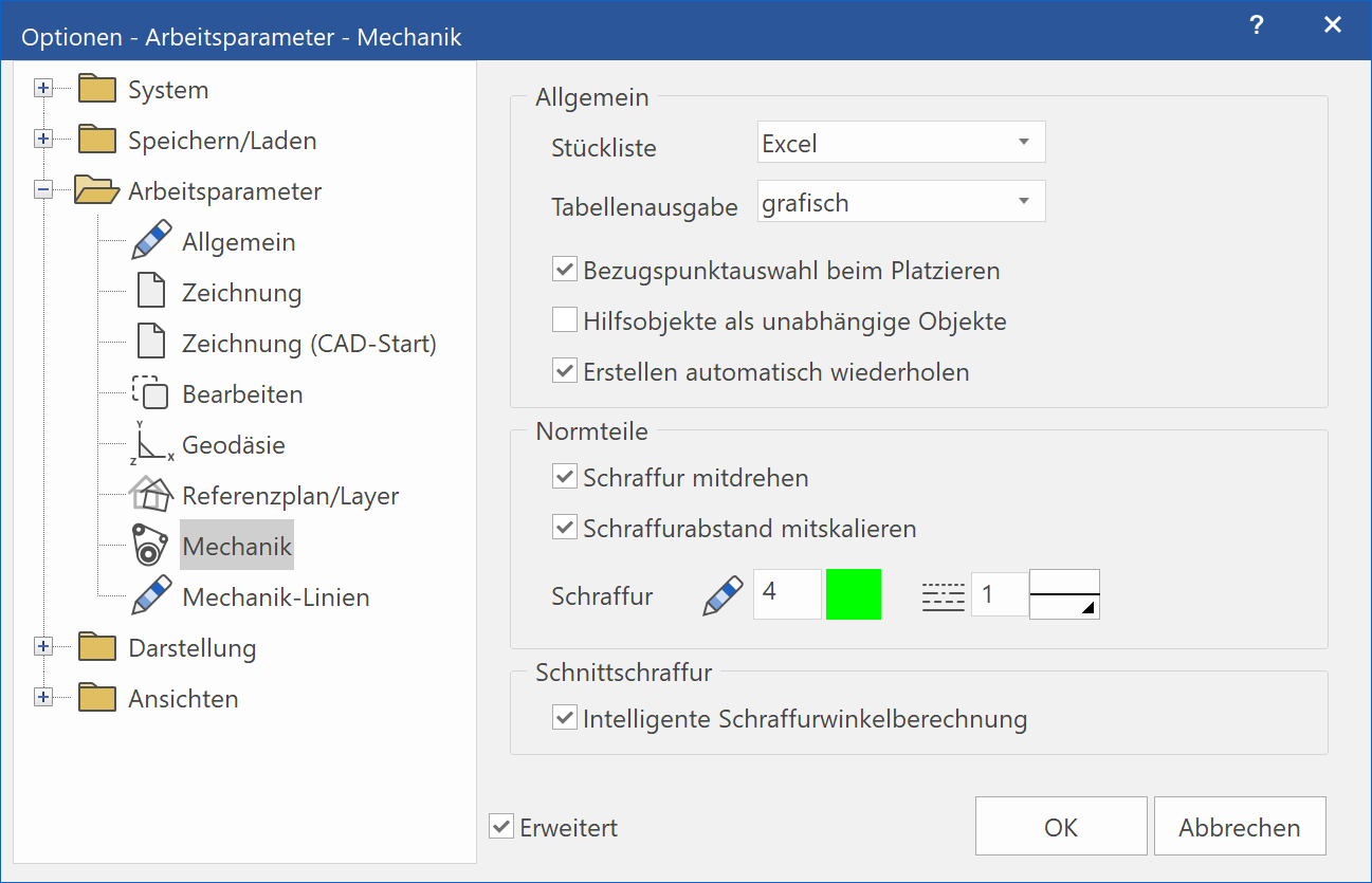
Mechanics – General – Bill of material
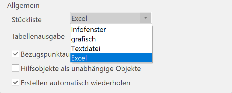
With ELITECAD, you currently have four possibilities to generate a bill of material:
-
Info window
Bills of material in the info window are used for a quick check of the entries and assigned attributes. Information printed in the info window are replaced by the subsequent output into the info window like object information. -
Graphic
A bill of material can be positioned into your ELITECAD drawing using the snap functions. A subdivision point is queried which is used to split long lists and the second part could be positioned on a different position. Use the Esc key in order to undo a split or positioning operation. The positioning operation of the bill of material is completed with the Enter key.
By opening the bill of material function again further modifications can be made. The complete bill of material can be selected with the mouse and repositioned with the manipulation function or it can be deleted by selecting it and pressing the Del key.
Bill of material drawings (<ELITECAD installation path>\u\<version>\me\glob\l\table\bom_def_standard.d and bom_tail_standard.d) can be adjusted to your needs. These ELITECAD files define the layout of the bill of material by the drawn geometry, the elements (pen/line type) and texts (size, colour, reference point, etc.).
-
Text file
After having defined the file name for the bill of material, it is opened with an editor (Notepad) for checking. The bill of material definition file (<ELITECAD installation path>\u\<version>\me \glob\dflt\mecha.bom) can be adjusted with a text editor. -
Excel
See chapter Bill of Material > Create bill of material, section Excel..
Mechanics – General – Table output
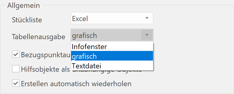
With ELITECAD, you currently have three possibilities to display calculation results and other data:
- Info window
Data is displayed in the info window for quick checks. - Graphic
Data is positioned as a table into the drawing - Text file
Data is written into a specified ASCII-file
This setting is valid for the output of the following tables:
- Tolerance table
- Fittings table
- Calculation results for moments of inertia
- Calculation results for area
These options have no influence on the results of the measure functions.
The results are always displayed in the CAD info window.
Mechanics – General – Reference point selection during placement

![]()
Mechanics – General – Helper objects as independent objects

Mechanics – Standard parts
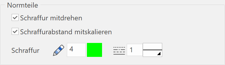
In this part of the dialog window, settings dictating how standard part hatches are affected by manipulation functions as well as pen colour and line type can be set.
Mechanics lines
These options are only available in ELITECAD Mechanics.
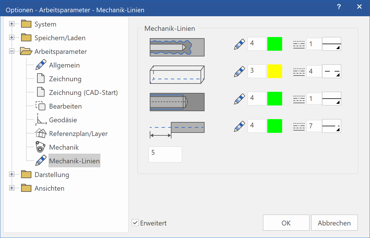
Mechanics lines – break lines

This is the setting for the line parameters (pen and line type) for the depiction of break lines of partial sections and detail cut-outs.
Mechanics lines – hidden lines

This is the setting for the line parameters (pen and line type) for the depiction of hidden lines of invisible component contours.
Mechanics lines – thread lines

This is the setting for the line parameters (pen and line type) for the depiction of thread lines of standard parts.
Mechanics lines – centre lines

This is the setting for the line parameters (pen and line type) for the depiction and the extent over the component boundaries for centre lines of rotational objects and circle centre lines.