Bearings
Under bearings you will find a large number of rolling bearings that are supported by supplier-neutral DIN tables. In contrast to the geometry data from relevant suppliers (ELITECAD PARTS / DVD / Internet), these rolling bearings are generated in accordance with DIN as ELITECAD objects and built into your design as separate components without conversion by interfaces (see also chapter Catalogue parts).
The most common types of bearings used in mechanical engineering can be called up directly with ELITECAD using their DIN standard and then inserted into the construction.
Create bearing
|
|
Standard parts toolbar |
| ME-Objects menu > Standard parts > Bearing |
With a click on the function TOOLS > STANDARD PARTS > CREATE BEARING in the toolbar or by selecting ME OBJECTS > STANDARD PARTS > BEARING in the menu bar, the settings of the last bearing drawn are active in the parameter window and the standard part can be set immediately.
Bearings property bar

The property bar is visible as soon as an existing bearing is selected for editing. Clicking on the bearing activates the property bar and the main values of the depiction of the bearing can be manipulated. Using the icon ![]() , the associated parameter window opens and all available values of the bearing can be modified.
, the associated parameter window opens and all available values of the bearing can be modified.
![]()
Roller bearings
| Image | DIN Standard | Range |
|---|---|---|
| DIN ISO 355 Metric tapered roller bearings, boundary dimensions and series designations | Bore Ø 15 to 360 | |
| DIN 720 Tapered roller bearings | Bore Ø 15 to 360 | |
| DIN 722 Thrust cylindrical roller bearings - single-direction | Bore Ø 15 to 600 | |
| DIN 728 Self-aligning thrust bearings - single-direction, with asymmetrical rollers | Bore Ø 60 to 1060 | |
| DIN 635-1 Radial roller bearings - part 1: single row with cylindrical and tapered bore (barrel roller bearings) | Bore Ø 20 to 280 | |
| DIN 635-2 Radial spherical roller bearings – part 2: double row with cylindrical and tapered bore | Bore Ø 20 to 600 | |
| DIN 5412-1 Cylindrical roller bearings – part 1: single row with cage, separate thrust collars | Bore Ø 15 to 556 | |
| DIN 5412-4 Ring-cylindrical bearings, double row | Bore Ø 25 to 710 | |
| DIN 5412-9 Cylindrical roller bearings, double row, full roller bearings, non-separable; dimension series 48 and 49 | Bore Ø 60 to 500 |
Groove ball bearings
| Image | DIN Standard | Range |
|---|---|---|
| DIN 625-1 Radial deep groove ball bearings - part 1: single row | Bore Ø 1.5 to 600 | |
| DIN 625-3 Radial deep groove ball bearings - part 3: double row | Bore Ø 10 to 90 | |
| DIN 625-4 Radial deep groove ball bearing - part 4: with flanged outer ring | Bore Ø 0.6 to 180 | |
| DIN 626-1 Rolling bearings with spherical outer surface and extended inner ring width – part 1: insert bearings | Bore Ø 12 to 100 | |
| DIN 626-2 Rolling bearings with spherical outer surface and extended inner ring width – part 2: housing for insert bearings | Bore Ø 12 to 100 | |
| DIN 711 Rolling bearings – single direction thrust ball bearings | Bore Ø 8 to 360 | |
| DIN 715 Rolling bearings – double direction thrust ball bearings | Bore Ø 10 to 190 |
Special ball bearings
| Image | DIN Standard | Range |
|---|---|---|
| DIN 628-1 Angular contact radial ball bearings - part1: single row, self-locking | Bore Ø 10 to 170 | |
| DIN 628-3 Angular contact radial ball bearings – part 3: double row | Bore Ø 10 to 110 | |
| DIN 628-4 Angular contact radial ball bearings - Part 4: single row, double-direction, not self-locking, with double-split inner ring (Four-point contact bearing) | Bore Ø 17 to 240 | |
| DIN 630 Self-aligning ball bearings - double row with cylindrical and tapered bore | Bore Ø 5 to 120 |
Special bearings
| Image | DIN Standard | Range |
|---|---|---|
| DIN 615 Magneto-type ball bearings – single row, not self-locking | Bore Ø 3 to 30 | |
| DIN 617 Needle roller bearings, with cage | Bore Ø 10 to 390 | |
| DIN 618-1 Needle roller bearings; drawn cups with open ends, drawn cups with closed end, with cage | Bore Ø 4 to 55 | |
| DIN 618-2 Needle roller bearings; drawn cups with open ends with cage, sealed | Bore Ø 14 to 50 | |
| DIN 736 Plummer block housings for rolling bearings of diameter series 2 with tapered bore and adapter sleeve | Shaft Ø 20 to 140 | |
| DIN 737 Plummer block housings for rolling bearings of diameter series 3 with tapered bore and adapter sleeve | Shaft Ø 20 to 75 | |
| DIN 738 Plummer block housings for rolling bearings of diameter series 2, with cylindrical bore | Shaft Ø 30 to 175 | |
| DIN 739 Plummer block housings for rolling bearings of diameter series 3, with cylindrical bore | Shaft Ø 30 to 95 | |
| DIN 981-1 Rolling bearing accessories - locknuts | Thread Ø 10 to 200 | |
| DIN 981-2 Rolling bearing accessories - locknuts | Thread Ø 220 to 1060 | |
| DIN 5429-1 Combined needle rolling bearings, Needle-thrust roller bearings, needle-thrust ball bearings | Bore Ø 10 to 50 | |
| DIN 5429-2 Combined needle rolling bearings, needle angular contact ball bearings | Bore Ø 12 to 60 |
Bearing accessories
| Image | DIN Standard | Range |
|---|---|---|
| DIN 983-1 Retaining rings with lugs for shafts (internal circlips) | Groove shafts Ø 16 to 140 | |
| DIN 983-2 Retaining rings with lugs for shafts (internal circlips) | Ring shafts Ø 16 to 140 | |
| DIN 984-1 Retaining rings with lugs (internal circlips) for use in bores | Groove shafts Ø 16 to 170 | |
| DIN 984-2 Retaining rings with lugs (internal circlips) for use in bores | Ring shafts Ø 16 to 170 | |
| DIN 5405-1 Needle rolling bearings-part 1: needle roller and cage assemblies | ||
| DIN 5405-2 Needle rolling bearings - part 2: thrust needle roller and cage assemblies | ||
| DIN 5405-3 Needle roller bearings - part 3: thrust washers | ||
| DIN 5406-1 Rolling bearings - lockwashers, safety plate, lockclips | ||
| DIN 5406-2 Roller bearings - lockwashers, safety plate, lockclip | ||
| DIN 5415 Rolling bearings, adapter sleeves | Sleeves Ø 17 to 1000 | |
| DIN 5417-1 Securing parts for rolling bearings - snap rings for bearings with ring | Groove shafts Ø 30 to 250 | |
| DIN 5417-2 Securing parts for rolling bearings - snap rings for bearings with ring groove | Ring shafts Ø 30 to 250 | |
| DIN 5419 Seals for bearing housings - felt rings, felt strips and ring grooves | Inside Ø 18 to 182 |
 Depiction (see General parameters)
Bearings parameters
![]()


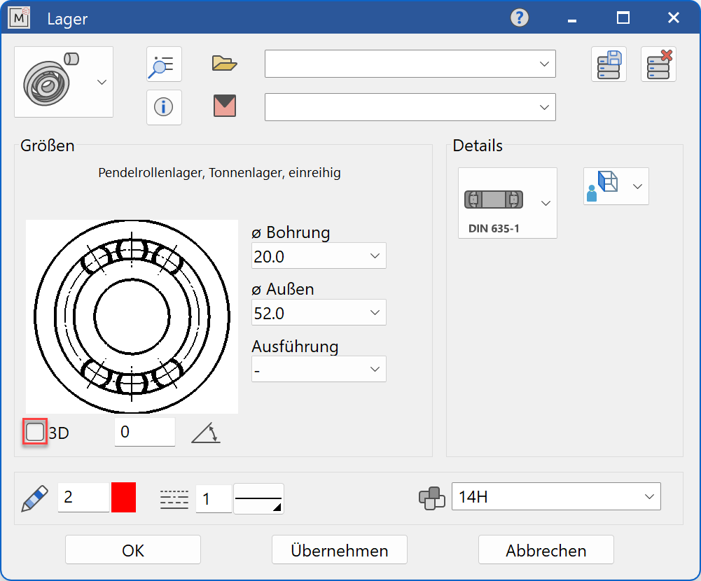
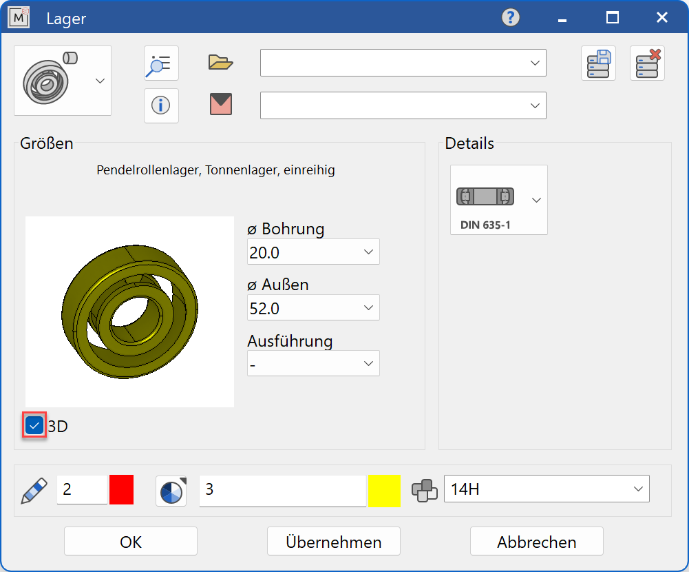
Decide whether the bearing should be depicted in 2D or 3D.
Tip
Specify the shaft diameter (bore) value first and then the outer diameter. Possible variants for the bearing width and bearing shape are now offered. In general, only values are offered that are available in the selected standard.
The completed dialog is confirmed with  . This means that the bearing is dynamically active at the cursor for positioning in the drawing. The reference point is the intersection of the left bearing surface of the bearing with the bearing centre line.
The function is ended when it is positioned within the construction. The function call can be opened repeatedly for other bearings of the same type. The last input parameters are retained and are suggested the next time it is opened.
Display
Text field

Display of the standard designation of the standard part
Dimensions
Standard part group selection
Roller bearings
Groove ball bearings
Special ball bearings
Special bearings
Bearing accessories
Selection of the standard
Selection of the required standard from its respective group
Input values
The input fields available differ depending on the standard.
Bore diameter

Bore diameter of the bearing in standard increments
Shaft diameter

Shaft diameter of the bearing in standard increments
Thread diameter

Thread diameter for locknuts in standard increments
Nominal size

Nominal size of the bearing in standard increments
Outside diameter

Outside diameter of the bearing in standard increments
Total width

Total width of the bearing in standard increments
Abbreviation

The abbreviation is used as a concise name for bearings / bearing accessories. Some bearings or bearing accessories are only referred by their abbreviations.
Version

The version denotes different types of bearings.
Design

The design denotes different types of bearings.
Bearing shape

The bearing shape denotes different types of bearings.
Orientation angle
Angle of the bearing relative to the X-axis in the 2D representation
Alternatives

For the side view, the standard representation is the section through the bearing. If a view of the bearing from the outside is also offered, this can be set using the alternative.
Turn the page

Scroll in the direction of the arrow if there are several input windows