Fittings
Fittings are very frequently used elements for the detachable connection of pipeline parts or for the detachable insertion of armatures. In addition, fittings are also used to lay pipes and to seal off pipelines.
The most common fitting types used in mechanical engineering and plant construction can be called up directly with ELITECAD using their DIN standard and inserted into the construction.
Create fitting
|
|
Standard parts toolbar |
| ME-Objects menu > Standard parts > Fittings |
With a click on the function TOOLS > STANDARD PARTS > CREATE FITTING in the toolbar or by selecting ME OBJECTS > STANDARD PARTS > FITTING in the menu bar, the settings of the last fitting drawn are active in the parameter window and the standard part can be set immediately.
Fittings property bar

The property bar is visible as soon as an existing fitting is selected for editing. Clicking on the fitting activates the property bar and the main values for the fitting can be manipulated. Using the icon ![]() , the associated parameter window opens and all available values of the fitting can be modified.
, the associated parameter window opens and all available values of the fitting can be modified.
![]()
Straight fittings
![]()
| Image | DIN Standard | Range |
|---|---|---|
| DIN EN 10241-O Steel threaded steel pipe fittings | Thread 3/8ʺ to 6ʺ | |
| DIN EN 10241-Q Steel threaded pipe, parallel nipples with thread | Thread 3/8ʺ to 6ʺ | |
| DIN EN 10241-P Steel threaded pipe, parallel nipples with full-length thread | Thread 3/8ʺ to 6ʺ | |
| DIN EN 10241-H Steel threaded pipe, hexagon double nipples | Thread 3/8ʺ to 6ʺ | |
| DIN EN 10241-I Steel threaded pipe, hexagon reducing nipples | Thread 3/8ʺ to 6ʺ e.g. reduction 3/8ʺ to 5ʺ | |
| DIN EN 10241-E Steel threaded pipe, heavy-weight sockets | Thread 3/8ʺ to 6ʺ | |
| DIN EN 10241-F Steel threaded pipe, medium heavy-weight sockets | Thread 3/8ʺ to 6ʺ | |
| DIN EN 10241-G Steel threaded pipe, reducing sockets | Thread 3/8ʺ to 6ʺ e.g. reduction 1/4ʺ to 5ʺ | |
| DIN EN 10242-M Threaded fittings, malleable cast iron socket | Nominal diameter 6 to 150 | |
| DIN EN 10242-N Threaded fittings, malleable cast iron double nipple, reduced | Nominal diameter 6 to 100 reduction depending on DN | |
| DIN EN 10241-U Threaded fittings, malleable cast iron screw connection | Thread 3/8ʺ to 4ʺ | |
| DIN 2616-1 Steel eccentric reducer for butt-welding with reduced pressure factor | Outside pipe diameter 21.3 to 1220.0 | |
| DIN 2616-2 Steel reducer for butt-welding with full service pressure | Outside pipe diameter 21.3 to 1220.0 |
Curved fittings
![]()
| Image | DIN Standard | Range |
|---|---|---|
| DIN 2605-1 Steel elbow for butt-welding with reduced pressure factor | Outside pipe diameter 21.3 to 1620,0 | |
| DIN 2605-2 Steel elbow for butt-welding full service pressure | Outside pipe diameter 21.3 to 1620,0 | |
| DIN EN 10241-R Steel threaded pipe, bends | Nominal diameter 8 to 150 | |
| DIN EN 10242-A Threaded fittings, malleable cast iron elbow | Nominal diameter 6 to 150 | |
| DIN EN 10242-D Threaded fittings, malleable cast iron short radius elbow | Nominal diameter 8 to 50 | |
| DIN EN 10242-G Threaded fittings, malleable cast iron long radius elbow | Nominal diameter 8 to 100 | |
| DIN EN 10242-W Threaded fittings, malleable cast iron elbow with threaded connection | Thread 3/8ʺ to 2ʺ |
Branch fittings
![]()
| Image | DIN Standard | Range |
|---|---|---|
| DIN 2615-1 Steel tees for butt-welding with reduced pressure factor | Outside pipe diameter 21.3 to 1220.0 | |
| DIN 2615-2 Steel tees for butt-welding with full service pressure | Outside pipe diameter 21.3 to 1220.0 | |
| DIN 10241-A Steel threaded pipe, crosses, tees or elbows | Nominal diameter 6 to 150 | |
| DIN 10241-D Steel threaded pipe, reducing tees | Thread 3/8ʺ to 6ʺ | |
| DIN 10242-B Threaded fittings, malleable cast iron tee | Nominal diameter 6 to 150 | |
| DIN 10242-C Threaded fittings, malleable cast iron cross | Nominal diameter 8 to 100 | |
| DIN 10242-E Threaded fittings, malleable cast iron tee | Nominal diameter 10 to 50 | |
| DIN 10242-Z Threaded fittings, malleable cast iron 3-way elbow | Nominal diameter 10 to 25 |
Accessories
![]()
| Image | DIN Standard | Range |
|---|---|---|
| DIN 2617 Steel caps for butt-welding | Outside pipe diameter 26.9 to 4000.0 | |
| DIN EN 10241-J Steel threaded pipe, plug | Nominal diameter 6 to 150 | |
| DIN EN 10241-N Steel threaded pipe, cap | Nominal diameter 6 to 150 | |
| DIN 28011 Torispherical heads (dished end) | Outside pipe diameter 26.9 to 4000.0 | |
| DIN 28013 Ellipsoidal heads (dished end) | Outside pipe diameter 26.9 to 4000.0 | |
| DIN EN 10242-P Threaded fittings, malleable cast iron locknut | Nominal diameter 8 to 80 | |
| DIN EN 10242-T Threaded fittings, malleable cast iron plug | Nominal diameter 6 to 100 |
 Depiction (see General parameters)
Fitting parameters
![]()
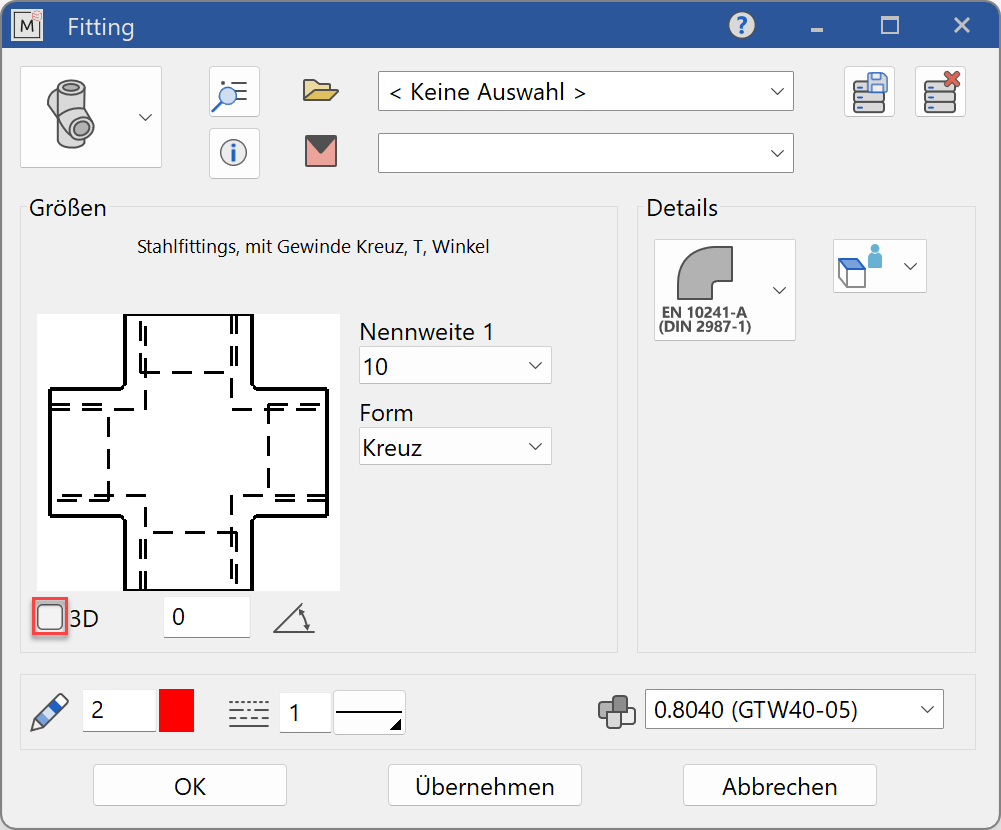
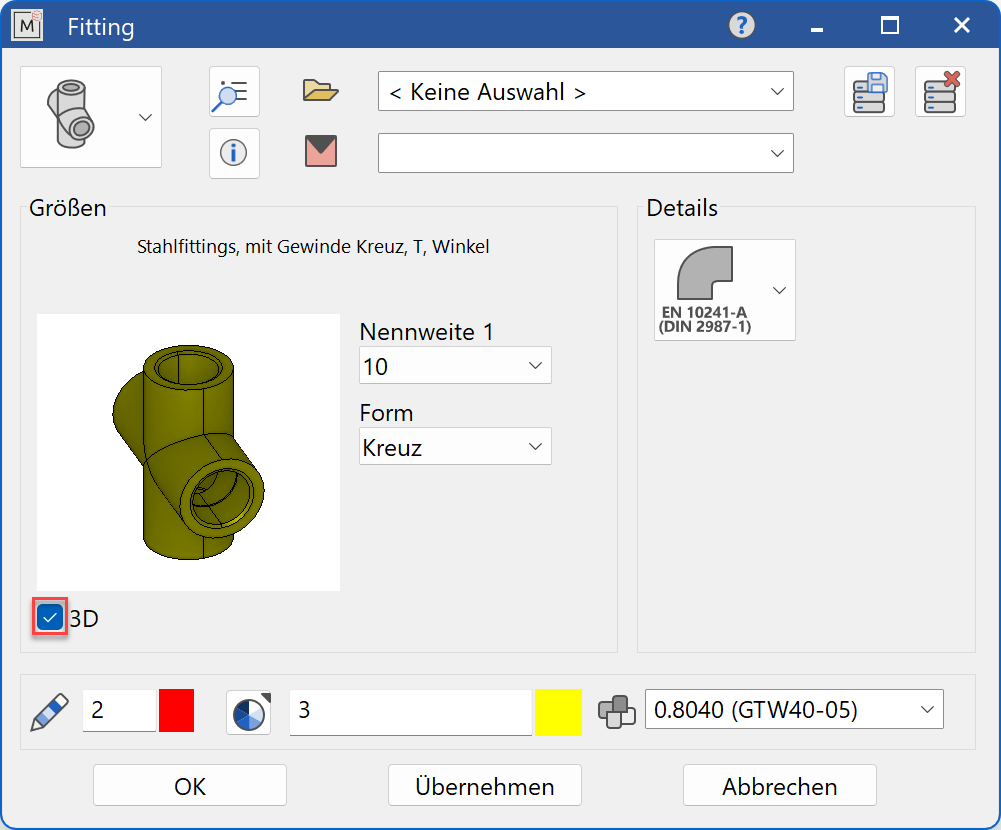
Decide whether the fitting should be created in 2D or in 3D.
Tip
Specify the nominal diameter value first and only then the values for the other selection parameters. The selection windows will only offer values that are available to the selected standard.
The completed dialog is confirmed with  . This means that the fitting is dynamically active at the cursor for positioning in the drawing. The reference point depends on the type of fitting, with the pipe centre axis usually serving as the reference point. The function is ended when it is positioned within the construction.
The function can be opened repeatedly for further fittings of the same type. The last input parameters are retained and are suggested the next time it is opened.
Display
Text field

Display of the standard designation of the fitting
Dimensions
Standard part group selection
![]() Straight fittings
Straight fittings
![]() Curved fittings
Curved fittings
![]() Branch fittings
Branch fittings
![]() Accessories
Accessories
Selection of the standard
![]()
Selection of the required standard from its respective group
Input values
The input fields available differ depending on the standard.
Thread
Thread in inches of the fitting in standard increments
Thread 1 in inches of the fitting in standard increments
Always indicates the larger diameter of a reduced fitting.
Thread 2 in inches of the fitting in standard increments
Always indicates the smaller diameter of a reduced fitting.
Form
The form of the fitting indicates the respective construction. This can be, for example, long thread - Langgewinde, double long thread - Doppeltes Langgewinde, nipple - Nippel, threaded nipple - Gewindenippel, pipe double nipple - Rohrdoppelnippel, cross - Kreuz, Tee-piece - T-Stück or angle - Winkel.
Design

The design indicates whether it is a medium-heavy - Mittelschwer or heavy-duty - Schwer version of the fitting.
Overall length
Overall length of the fitting in standard increments
Nominal diameter
Nominal diameter of the fitting in standard increments
Abbreviation
The type of fitting is often specified with a short code (abbreviation). Designations such as M2, N8, U1, U2, U11 or U12 are used. See also ISO 49 / EN 10242.
Wrench size

Wrench size of the fittings
Outside pipe diameter
Outside pipe diameter of the fitting in standard increments
Outer diameter
Outside diameter of the fitting in standard increments
Wall thickness
Wall thickness of the fitting in standard increments
Series

Indicates the preferred series according to DIN, whereby the term is hardly used anymore.
Type

The type of fitting indicates whether it is seamless - nahtlos or welded - geschweisst.
Design type
In the case of pipe bends, the design type indicates which bend diameter is present. The number e.g. 3 indicates that the bend radius corresponds to 3 x the pipe outer diameter.
Installation angle
In the case of pipe bends, the installation angle indicates which bend is present in relation to the angle length (45°, 90° or 180°).
Angle
In the case of pipe bends, the angle indicates which bend is present in relation to the angular length (90°, 112.5°, 135° or 157.5°)..
Connection thread
The connection thread indicates the thread dimension of the pipe connections in standard increments and depending on the nominal diameter.
Flange edge
With torispherical and ellipsoidal heads , the flange edge indicates the characteristics of the weld seam preparation. Form R stands for unprocessed flange edge, the remaining forms correspond to the respective weld seams. The flange edge shape is not shown.
Orientation angle
![]()
Angle of the fitting relative to the X-axis in the 2D representation
Turn the page

Scroll in the direction of the arrow if there are several input windows