Flanges
Flanges are very frequently used elements for the detachable connection of pipeline parts or for the detachable insertion of fittings. Flanges are also used to seal off pipelines.
The most common flange types used in mechanical engineering and plant construction can be called up directly with ELITECAD using their DIN standard and then inserted into the construction.
Create flange
|
|
Standard parts toolbar |
| ME-Objects menu > Standard parts > Flange |
With a click on the function TOOLS > STANDARD PARTS > CREATE FLANGE in the toolbar or by selecting ME-OBJECTS > STANDARD PARTS > FLANGE in the menu bar, the settings of the last flange drawn are active in the parameter window and the standard part can be set immediately.
Flanges property bar

The property bar is visible as soon as an existing flange is selected for editing. Clicking on the flange activates the property bar and the main values of the flange can be manipulated. Using the icon ![]() , the associated parameter window opens and all available values of the flange can be modified.
, the associated parameter window opens and all available values of the flange can be modified.
![]()
Welding neck flanges
![]()
| Image | DIN Standard | Range |
|---|---|---|
| DIN 2627 Welding neck flanges | Nominal diameter 10 to 200, Nominal pressure 400 |
|
| DIN 2628 Welding neck flanges | Nominal diameter 15 to 250, Nominal pressure 250 |
|
| DIN 2629 Welding neck flanges | Nominal diameter 10 to 250 Nominal pressure 320 |
|
| DIN 2638 Welding neck flanges | Nominal diameter 10 to 300, Nominal pressure 160 |
Steel flanges
![]()
| Image | DIN Standard | Range |
|---|---|---|
| DIN EN 1092-1 Type 01, Plate flange for welding | Nominal diameter 10 to 2000, Nominal pressure 2.5 to 100 |
|
| DIN EN 1092-1 Type 02, Loose plate flanges with weld-on plate collar | Nominal diameter 10 to 600, Nominal pressure 6 to 40 |
|
| DIN EN 1092-1 Type 04, Loose plate flanges with weld-neck collar | Nominal diameter 10 to 600, Nominal pressure 10 to 40 |
|
| DIN EN 1092-1 Type 05, Blind flange | Nominal diameter 10 to 2000, Nominal pressure 2.5 to 100 |
|
| DIN EN 1092-1 Type 11, Welding neck flange | Nominal diameter 10 to 4000, Nominal pressure 2.5 to 100 |
|
| DIN EN 1092-1 Type 12, Hubbed slip-on flanges for welding | Nominal diameter 10 to 600, Nominal pressure 6 to 100 |
|
| DIN EN 1092-1 Type 13, Hubbed threaded flange | Nominal diameter 10 to 150, Nominal pressure 6 to 100 |
|
| DIN EN 1092-1 Type 21, Integral flange | Nominal diameter 10 to 2000, Nominal pressure 6 to 100 |
|
| DIN EN 1092-1 Type 32, Weld-on collar plate | Nominal diameter 10 to 600, Nominal pressure 6 to 40 |
|
| DIN EN 1092-1 Type 33, Welding neck collars | Nominal diameter 10 to 600, Nominal pressure 6 to 40 |
|
| DIN EN 1092-1 Type 34, Weld-neck collars | Nominal diameter 10 to 600, Nominal pressure 6 to 40 |
 Depiction (see General parameters)
Flange parameters
![]()
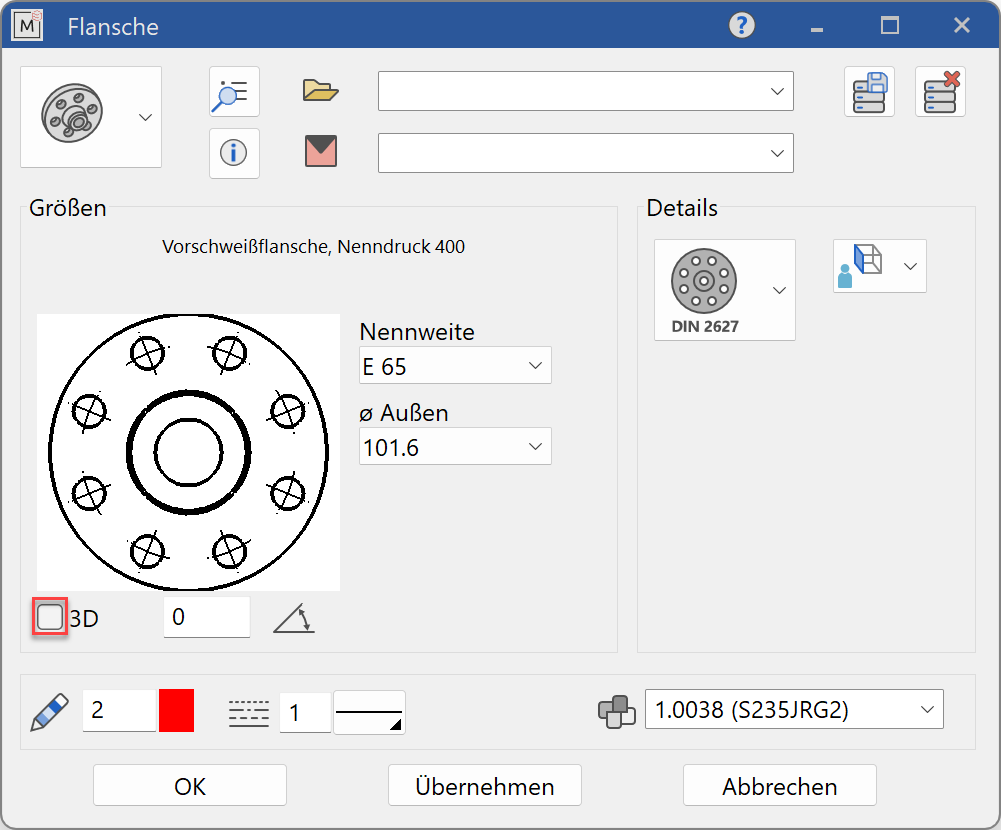
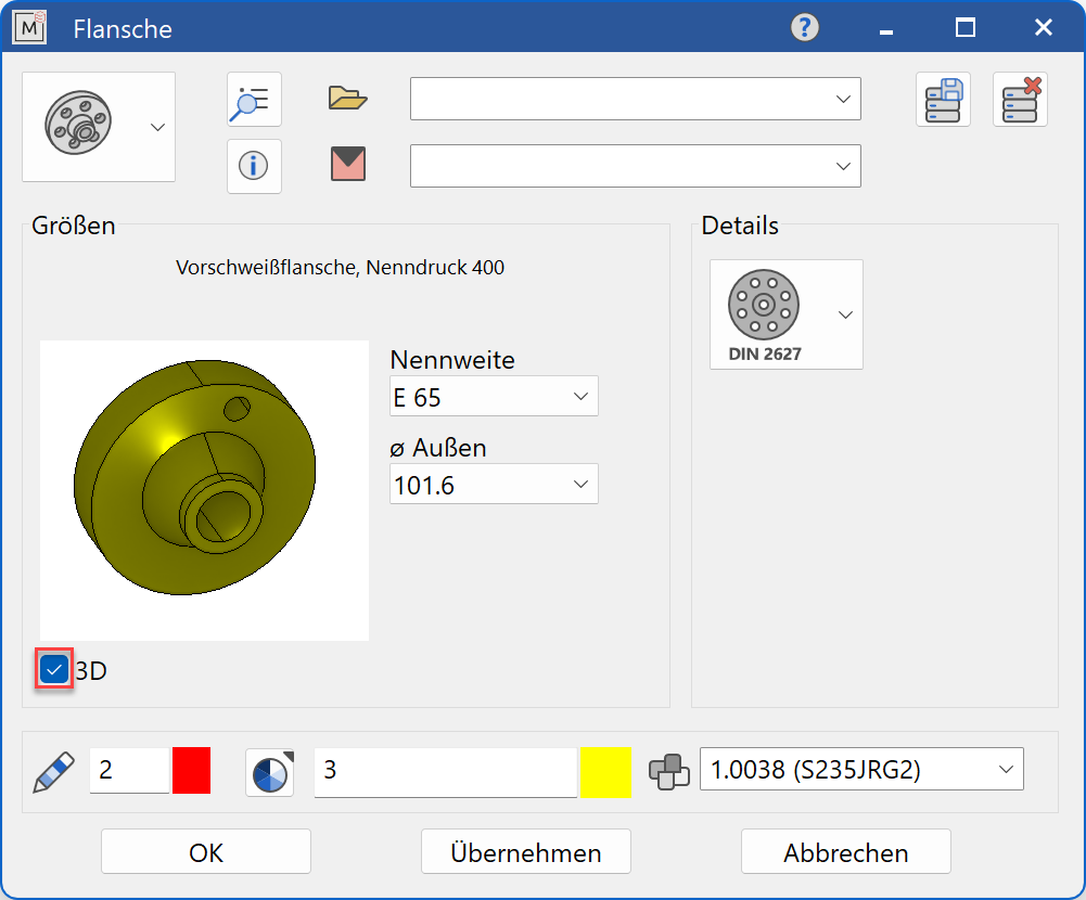
Decide whether the flange should be created in 2D or 3D.
Tip
Specify the nominal diameter value first and then the values for the other selection parameters. The selection windows will only offer values that are available to the selected standard.
The completed dialog is confirmed with  . This means that the flange is dynamically active at the cursor for positioning in the drawing. The reference point is the intersection of the pipe centre axis with the sealing surface of the flange.
The function is ended when it is positioned within the construction. The function can be opened repeatedly for other identical flanges. The last input parameters are retained and are suggested the next time it is opened.
Display
Text field

Display of the standard designation of the standard part
Dimensions
Standard part group selection
![]() Welding neck flange
Welding neck flange
![]() Steel flanges
Steel flanges
Selection of the standard
![]()
Selection of the required standard from its respective group
Input values
The input fields available differ depending on the standard.
Nominal diameter
Nominal diameter of the flange in standard increments
Nominal pressure

Nominal pressure of the flange in standard increments
Sealing surface shape

The shape of the sealing surface is offered in different designs for the respective flange.
Outer diameter

Outside diameter of the flange
Inner diameter

Inside diameter of the flange does not correspond to the nominal width
Flanged plate thickness

Thickness of the flanged plate
Flange thickness

Thickness of the flange
Thread type

Thread type of the flange, whereby the input Rc (conical, oblique) or Rp (cylindrical, straight) is possible.
straight- gerade and angled - schräg are also possibilites depending on which Norn is selected.
Orientation angle
![]()
Angle of the flange relative to the X-axis in the 2D representation
Turn the page

Scroll in the direction of the arrow if there are several input windows.