Nuts
Nuts, along with screws, are the most common elements used to connect components. Nuts and their threads are largely standardized. They are used both as individual parts, e.g. weld nuts, and in combination with screws and washers as screwings.
The most common nut types used in mechanical engineering can be called up directly with ELITECAD with their DIN standard and inserted into the construction.
Create nuts
|
|
Standard parts toolbar |
| ME-Objects menu > Standard parts > Nut |
With a click on the function TOOLS > STANDARD PARTS > CREATE NUT in the toolbar or by selecting ME-OBJECTS > STANDARD PARTS > NUT in the menu bar, the settings of the last nut drawn are active in the parameter window and the standard part can be placed immediately.
Nuts property bar

The property bar is visible as soon as an existing nut is selected for editing. With a click on the nut, the property bar is activated and the main values of the depiction of the nut can be manipulated. Using the icon ![]() , the associated parameter window opens and all available values of the nut can be modified.
, the associated parameter window opens and all available values of the nut can be modified.
Nuts
![]()
| Image | DIN Standard | Range |
|---|---|---|
| DIN 315 Wing nuts, rounded shape | M 4 to M 24 | |
| DIN 582 Lifting eye nuts | M 8 to M 100 | |
| DIN 928 Square weld nuts | M 4 to M 16 | |
| DIN 929 Hexagon weld nuts | M 3 to M 16 | |
| DIN EN 14399-4 Hexagon nuts with large widths across flats for high strength structural bolting (HV systems) | M 12 to M 36 | |
| DIN EN ISO 4032 Hexagon regular nuts (style 1), product grade A and B | M 1.6 to M 64 | |
| DIN EN ISO 4034 Hexagon regular nuts, product grade C | M 5 to M 64 | |
| DIN EN ISO 4035 Hexagon thin nuts champfered, product grade A and B | M 1.6 to M 64 | |
| DIN EN ISO 4036 Hexagon thin nuts unchamfered, product grade B | ||
| DIN 917 Hexagon cap nuts, low type | M 4 to M 72 | |
| DIN 1587 Hexagon domed cap nuts, high type | M 4 to M 24 | |
| DIN EN 10511 Prevailing torque type hexagon thin nuts (with non-metallic insert) |
 Depiction (see General parameters)
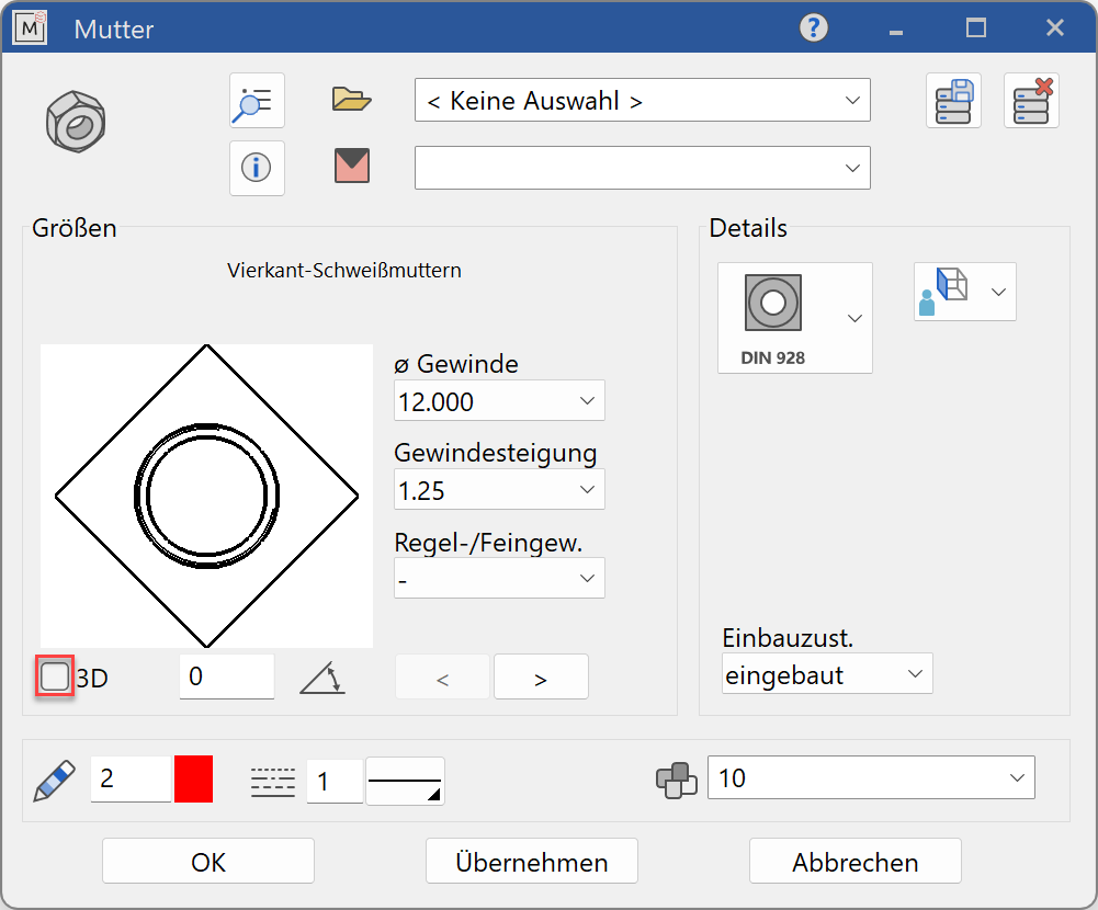
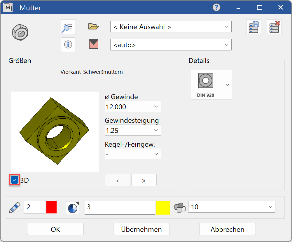
Nut parameters
![]()


Decide whether the nut should be created in 2D or in 3D.
Tip
Specify the thread diameter first value and then the other values. The selection windows will only offer values that are available according to the selected standard.
The completed dialog is confirmed with  . This means that the nut is dynamically active at the cursor for positioning in the drawing. The reference point is the intersection of the support surface with the nut centre line. The function is ended when it is positioned within the construction.
The function can be opened repeatedly for other nuts of the same type. The last input parameters are retained and are suggested the next time it is opened.
Display
Text field

Selection of the required standard from its respective group
Dimensions
Selection of the standard
Display of the standard designation of the standard part
Input values
The input fields available differ depending on the standard.
Thread diameter

Thread diameter of the nut in standard increments
Thread pitch

Thread pitch according to availability in the respective standard
Coarse / fine thread

Selection of thread type: coarse or fine thread Option availability depends on in the respective standard
Orientation angle
Angle of the screw relative to the X-axis in the 2D representation
Turn the page

Scroll in the direction of the arrow if there are several input windows