Pins and Bolts
Pins and bolts are frequently used elements for the positive connection of components. Pins serve as a radial position fixation or as an adjusting element for fine adjustments. Bolts connect two elements (e.g. joints) positively and flexibly. The most common pin types and bolt types used in mechanical engineering can be called up directly with ELITECAD via their DIN standard and inserted into the construction.
Create pins and bolts
|
|
Standard parts toolbar |
| ME-Objects menu > Standard parts > Pins |
With a click on the function TOOLS > STANDARD PARTS > CREATE PINS in the toolbar or by selecting ME-OBJECTS > STANDARD PARTS > PINS in the menu bar, the settings of the last pin / bolt drawn are active in the parameter window and the standard part can be set immediately.
Pins and bolts property bar

The property bar is visible as soon as an existing pin / bolt is edited. Clicking on the pin / bolt activates the property bar and the main values of the depiction of the pin / bolt can be manipulated. Using the icon ![]() , the associated parameter window opens and all available values of the pin / bolt can be modified.
, the associated parameter window opens and all available values of the pin / bolt can be modified.
![]()
Set screws
![]()
| Image | DIN Standard | Range |
|---|---|---|
| DIN EN ISO 4026 Hexagon socket set screws with flat point | Ø 1.4 to 24 | |
| DIN EN ISO 4027 Hexagon socket set screws with cone point | Ø 1.4 to 24 | |
| DIN EN ISO 4028 Hexagon socket set screws with dog point | Ø 1.4 to 24 | |
| DIN EN ISO 4029 Hexagon socket set screws with cup point | Ø 1.4 to 24 | |
| DIN EN ISO 24766 Slotted set screws with flat point | Ø 1.6 to 12 | |
| DIN EN ISO 27434 Slotted set screws with cone point | Ø 1.4 to 24 | |
| DIN EN ISO 27435 Slotted set screws with long dog point | Ø 1.6 to 24 | |
| DIN EN ISO 27436 Slotted set screws with cup point | Ø 1.6 to 24 |
Straight pins
![]()
| Image | DIN Standard | Range |
|---|---|---|
| DIN EN ISO 2338 Parallel pins of unhardened steel and austenitic stainless steel | Ø 0.6 to 50 | |
| DIN EN ISO 8733 Parallel pins with internal thread of unhardened steel and austenitic stainless steel | Ø 0.6 to 50 | |
| DIN EN ISO 8734 Parallel pins of hardened steel | Ø 1 to 20 | |
| DIN EN ISO 8735 Parallel pins with internal thread of hardened steel | Ø 6 to 50 |
Grooved pins/clamping sleeves
![]()
| Image | DIN Standard | Range |
|---|---|---|
| DIN EN ISO 8739 Full-length parallel grooved pins with pilot | Ø 1.5 to 25 | |
| DIN EN ISO 8740 Full-length parallel grooved pins with chamfer | Ø 1.5 to 25 | |
| DIN EN ISO 8752 Spring-type straight pins - slotted, heavy duty | Ø 1 to 50 | |
| DIN EN ISO 13337 Spring-type straight pins - slotted, light duty | Ø 2 to 50 |
Bolts
![]()
| Image | DIN Standard | Range |
|---|---|---|
| DIN EN 22340 Clevis pins without head | Ø 3 to 100 | |
| DIN EN 22341 Clevis pins with head | Ø 3 to 100 |
 Depiction (see General parameters)
Pins and bolts parameters
![]()
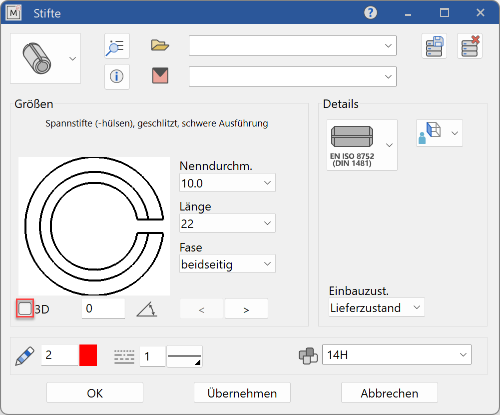
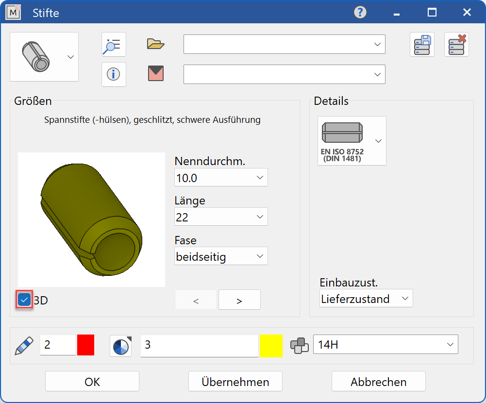
Decide whether the pin / bolt should be created in 2D or in 3D.
Tip
Specify the pin / bolt diameter value first and then the pin length and all other entries. The selection window will only offer pin / bolt dimensions that are available according to the selected standard.
Display
Text field

Display of the standard designation of the standard part
Dimensions
Standard part group selection
![]() Set screws
Set screws
![]() Straight pins
Straight pins
![]() Grooved pins/clamping sleeves
Grooved pins/clamping sleeves
![]() Bolts
Bolts
Selection of the standard
![]()
Selection of the required standard from its respective group
Input values
The input fields available differ depending on the standard.
Thread diameter
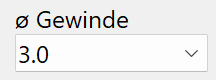
Thread diameter of the pin in standard increments (only with threaded pins)
Nominal diameter
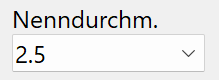
Nominal diameter of the pin/bolt in standard increments
Length

Length of the pin/bolt
Shape type
Execution of the pin/bolt according to the desired shape
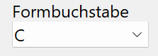
Form

Execution of the pin/bolt according to the desired shape
For the bolts options, choose whether a cotter pin hole is present Form B - mit Splitloch or not Form A - ohne Splitloch
Hardness
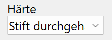
Indication of whether the pin is fully hardened - Stift durchgehärtet (Form A) or case-hardened - Stift einsatzgehärtet (Form B)
Tolerance class
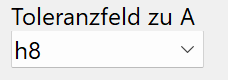
Specification of the tolerance field for production
Chamfer
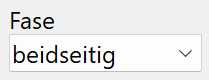
Indication of whether the chamfer is to be made on one - einseitig or both sides - beidseitig
Slot
Indication of the type of slot as normal - Normalfall or non-hooking - Nicht verhakend (Form N)
Orientation angle
![]()
Angle of the pin/bolt relative to the X-axis in the 2D representation
Turn the page

Scroll in the direction of the arrow if there are several input windows