Pipes
Pipes are very frequently used elements for the transport of a wide variety of liquids or gases. The transport of coal dust, for example, also takes place in highly pressured pipes.
The most common pipe types used in mechanical engineering and plant construction can be called up directly with ELITECAD using their DIN standard and then inserted into the construction.
Create pipe
|
|
Standard parts toolbar |
| ME-Objects menu > Standard parts > Pipes |
With a click on the function TOOLS > STANDARD PARTS > CREATE PIPES in the toolbar or by selecting ME OBJECTS > STANDARD PARTS > PIPES in the menu bar, the settings of the last pipe drawn are active in the parameter window and the standard part can be set immediately.
Pipes property bar

The property bar is visible as soon as an existing pipe is selected for editing. Clicking on the pipe activates the property bar and the main values of the depiction of the pipe can be manipulated. Using the icon ![]() , the associated parameter window opens and all available values of the pipe can be modified.
, the associated parameter window opens and all available values of the pipe can be modified.
![]()
Pipes
| Image | DIN Standard | Range |
|---|---|---|
| DIN EN 10255 Non-alloy steel pipes suitable for welding, threading and other joining methods | Outside pipe diameter 10.2 to 165.1 | |
| DIN EN 10220 Seamless and welded steel pipes, dimensions and masses per unit length | Outside pipe diameter 10.2 to 2540.0 |
 Depiction (see General parameters)
Pipe parameters
![]()


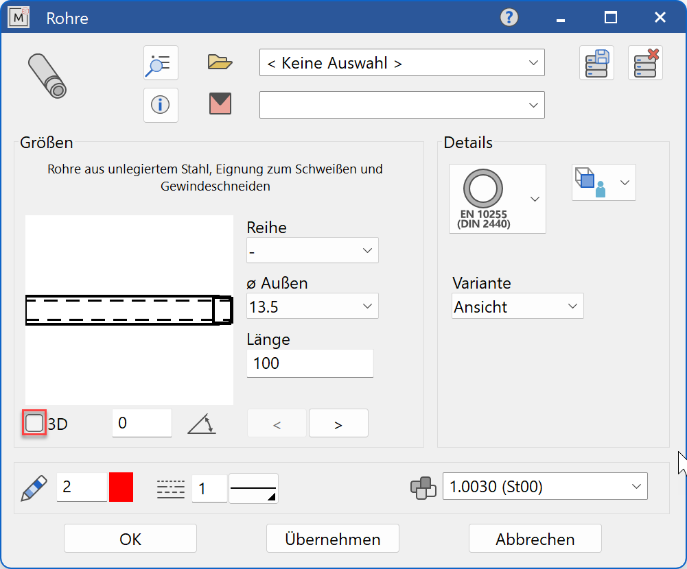
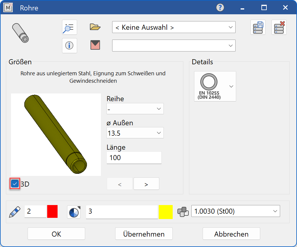
Decide whether the pipe should be created in 2D or in 3D.
Tip
Specify the nominal diameter value first and then the values for the other selection parameters. The selection window will only offer values that are available to the selected standard.
The completed dialog is confirmed with  . This means that the pipe is dynamically active at the cursor for positioning in the drawing. The reference point is the point of intersection of the end face of the pipe with the pipe centre axis.
The function is ended when it is positioned within the construction. The function can be opened repeatedly for other identical pipes. The last input parameters are retained and are suggested the next time it is opened.
Display
Text field

Display of the standard designation of the pipes
Input values
The input fields available differ depending on the standard.
Series

The pipes are produced in three series options, none (L), medium (M) and heavy (H).
or
Series

Specifies the preferred series according to DIN, whereby the term is rarely used and series 1 is considered the standard.
Outer pipe diameter

Outside pipe diameter of the pipe in standard increments
Length

Length of the pipe
Wall thickness

Wall thickness of the pipe in standard increments
Design

The design indicates whether the pipe is required with a thread - mit Gewinde or without a thread - ohne Gewinde.
Manufacturing process

The manufacturing process of the pipes differs in seamless (S) or welded (W) production.
View option

With the input field Alternatives, the cut - Schnitt or uncut - Ansicht depiction of the pipe can be selected.
Orientation angle
Angle of the pipe relative to the X-axis in the 2D representation
Turn the page

Scroll in the direction of the arrow if there are several input windows