Profiles
Like the base plates, profiles are frequently used components in the construction of machine frames, support brackets, inspections and platforms, etc. A multitude of possible applications supports this function of ELITECAD. In addition to the frequently used hot-rolled profiles such as I-profiles, U-profiles and L-profiles as well as common shaped full and hollow profiles, this function can be used to generate all types of folded cold profiles with free dimensions as well as a wide variety of extruded profiles as supports.
The most common profile types used in mechanical engineering can be called up directly with ELITECAD using their DIN standard and inserted into the construction.
Create profile
|
|
Standard parts toolbar |
| ME-Objects menu > Standard parts > Profiles |
With a click on the function TOOLS > STANDARD PARTS > CREATE PROFILES in the toolbar or by selecting ME OBJECTS > STANDARD PARTS > PROFILES in the menu bar, the settings of the last profile drawn are active in the parameter window and the standard part can be set immediately.
Profiles property bar

The property bar is visible as soon as an existing profile is selected for editing. Clicking on the profile activates the property bar and the main values of the depiction of the profile can be manipulated. Using the icon ![]() , the associated parameter window opens and all available values of the profile can be modified.
, the associated parameter window opens and all available values of the profile can be modified.
![]()
Hot-rolled I-beams
![]()
Made of steel grades according to DIN 17 100
| Image | DIN Standard | Range |
|---|---|---|
| DIN 1025-1 Hot-rolled, narrow flange I-beams, I-series with tapered flanges (inner surfaces) | Profile heights 80 bis 550 mm | |
| DIN 1025-2 Hot-rolled, wide flange I-beams, (IPB-series) with parallel flanges | Profile heights 100 bis 1000 mm | |
| DIN 1025-3 Hot-rolled, wide flange I-beams, IPBl-series light pattern with parallel flanges | Profile heights 100 bis 1000 mm | |
| DIN 1025-4 Hot-rolled, wide I-beams, IPBv-series heavy pattern with parallel flanges | Profile heights 100 bis 1000 mm | |
| DIN 1025-5 Hot-rolled, medium flange I-beams, (IPE-series) with parallel flanges | Profile heights 80 bis 600 mm | |
| DIN EN 10055 Hot-rolled, steel equal flange tees with radiused root and toes and tapered flanges (inner surface) | Profile heights 30 bis 140 mm |
Hot-rolled angle steel
![]()
Made of steel grades according to DIN 17 100
| Image | DIN Standard | Range |
|---|---|---|
| DIN 1022 Steel bars, hot-rolled, square-edged equal, angles (LS-steel) | Side width 20 bis 50 mm | |
| DIN EN 10056-1 Structural steel, equal and unequal, round-edged, steel angles | Side width 20 bis 250 mm |
Hot-rolled U and Z beams
![]()
Made of steel grades according to DIN 17 100
| Image | DIN Standard | Range |
|---|---|---|
| DIN 1026-1 Hot-rolled, round-edged, steel U-beams(channels) with tapered flange (inner surface) | U 30 bis U 400 | |
| DIN EN 10279 Hot-rolled, round-edged steel U-beams (channels) with tapered or parallel flanges | ||
| DIN 1027 Steel bars – Hot-rolled zees with round edges | Z 30 bis Z 200 |
Steel bars according to DIN
![]()
| Image | DIN Standard | Range |
|---|---|---|
| DIN EN 10060 Hot-rolled round steel bars | Ø 10 mm bis 250 mm | |
| DIN EN 10059 Hot-rolled square steel bars for general purposes | Side length 8 mm bis 150 mm | |
| DIN EN 10061 Hot-rolled hexagon steel bars | Diameter between the flats (Wrench size) 13 mm bis 103 mm | |
| DIN EN 10058 Hot-rolled steel flat steel bars for general purposes | Width 10 mm bis 150 mm | |
| DIN EN 10278-1 Bare flat steel | ||
| DIN EN 10278-2 Polished round / hexagon / square steel |
Shaped hollow profiles according to DIN
![]()
Made of steel grades according to DIN 17 100
| Image | DIN Standard | Shapes |
|---|---|---|
| DIN EN 10210-2 Hot-finished steel structural hollow sections | elliptical circular square rectangular |
|
| DIN EN 10219-2 Cold-formed welded steel structural hollow sections | circular square rectangular |
 Depiction (see General parameters)
Profile parameters
![]()

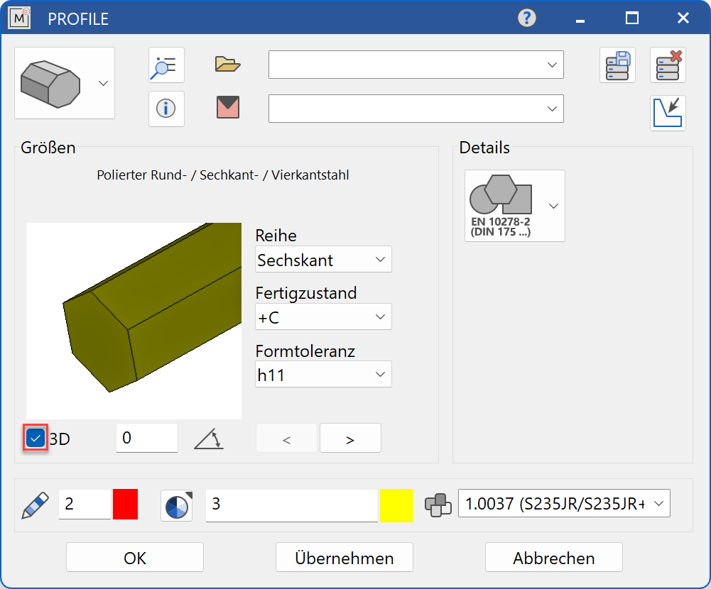
Decide whether the profile should be created in 2D or in 3D.
Once all parameters have been entered, the completed dialog is confirmed with  . This profile is then placed using the cursor snap functions. When asked for the reference point, the profile is still moved relative to the already selected placement point and the possible placement points are the corner points and the cross-sectional centre of the profile.


If the switch for the creation of standard parts in 3D is activated, the start point and end point for the profile length are queried. Then the 3D standard part is placed using the placement point.
The function is self-retaining and now allows the positioning of another profile of the same size. The function is ended by pressing the  function button or by pressing the Esc key. The function can be opened repeatedly for other profiles of the same type. The last input parameters are retained and are suggested the next time it is opened.
Display
Text field

Display of the standard designation of the standard part
Dimensions
Standard part group selection
![]() Hot-rolled I-beams
Hot-rolled I-beams
![]() Hot-rolled angles
Hot-rolled angles
![]() Hot-rolled U and Z beams
Hot-rolled U and Z beams
![]() Steel bars according to DIN
Steel bars according to DIN
![]() Hollow profiles according to DIN
Hollow profiles according to DIN
Selection of the standard
![]()
Selection of the required standard from its respective group
Input values hot-rolled beams
The input fields available differ depending on the standard.
Abbreviation
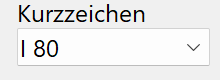
Abbreviation of the beam in standard increments
Form
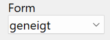
The form indicates whether the inside of the flange is inclined - geneigt or parallel - parallel.
Height
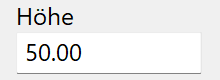
Height of the profile
Height
Height of the profile in standard increments (with specified values)
Width
Width of the profile
Flange thickness
Flange thickness of the profile
Web thickness
Web thickness of the profile
Orientation angle
![]()
Angle of the profile relative to the X-axis in the 2D representation
Turn the page

Scroll in the direction of the arrow if there are several input windows
View depiction
Input values solid profiles
The input fields available differ depending on the standard.
Diameter
Diameter of the round steel in standard increments
Side length
Side length of the square steel in standard increments
Wrench size

Wrench size of the hexagonal steel in standard increments
Dimensional deviation
Permissible dimensional deviation according to the standard
Width
Width of the profile
Total thickness
Total thickness of the flat bar in standard increments
Series
The "series" determines which shape the profile should have. The shapes "round" - Rund, "hexagon" - Sechskant and "square" - Vierkant are available for this.
Manufacturing condition
Indicates the condition of the surface according to standard criteria.
Shape tolerance
Permissible tolerance for the dimensions of the profile
Ø/side length/WS
Dimension of the profile depending on the shape of the profile entered under "Series".
Orientation angle
![]()
Angle of the profile relative to the X-axis in the 2D representation
Turn the page
Scroll in the direction of the arrow if there are several input windows
View depiction
Input values hollow profiles
Shape
The "shape" determines which type of profile is required. The shapes "elliptical" - Elliptisch, "circular" - Kreisförmig, "square" - Quadratisch and "rectangular" - Rechteckig are available for this.
Ø outer/height
Dimension of the profile depending on the type of profile entered under "shape".
Outer width
Outside width of the profile in standard increments
Wall thickness
Wall thickness of the profile in standard increments
Orientation angle
![]()
Angle of the profile relative to the X-axis in the 2D representation
Turn the page
Scroll in the direction of the arrow if there are several input windows
View depiction
Modify profile
The easiest way to change standard parts that have already been generated is to select the object with the mouse. The property bar of the standard part appears with the most important parameters. With a double-click on the object, the large parameter window is also opened and all current input values are displayed. Other options for opening the parameter window are the function MODIFY > ME-OBJECT or choosing EDIT in the context menu EDIT on the current selection.
Profiles can be selected and changed again after creation by clicking on them. Various handles and grippers are displayed on the profile with which the profile can be manipulated. The possible manipulations depend on the selected handle/gripper:
Square handles
Square handles are displayed on the 2D contour of the profile and allow the following manipulations:
![]()
Moving the profile – the point used to move the profile is selected at any handle.


![]()
Scaling the profile – the point at which the profile is scaled is selected at any handle. By dragging with the cursor, the scaling is carried out in the increments on which the standard is based.

Triangular handles
Triangular handles (height handles) are used to change the length of the profile. The Tab -Taste key can be used to switch between handle and gripper. This change in length can be carried out in different ways and allow the following manipulations:
![]()
Change height – the point that is used to lengthen/shorten the profile is selected on any handle. It can be any point on the screen or a point from an existing construction that is not on the profile.

![]()
Plane by 3 Points – 3 points are queried that define the plane that is used for the extension/shortening. After entering the second point, ELITECAD shows a preview of the selected result and the function is completed by entering the third point.

![]()
Tilt plane – the point that is used to tilt the profile surface is selected at any handle. Two more points are now queried that define the axis of rotation. The cross-section can now be tilted around this axis of rotation by dragging it with the cursor.

![]()
Adopt plane from surface - the profile that is used for extension/shortening is selected at any handle. A planar surface is now selected (can also be part of a box) up to which the profile should be extended/shortened. ELITECAD shows a preview of the selected result and another click completes the function.

![]()
Miter – the profile that is used for the miter is selected at any handle. A second profile is now selected up to which the profile should be extended/shortened. ELITECAD shows a preview of the selected result and another click completes the function, whereby the side of the profile that is clicked on remains.


![]()
Moving the profile – see «Square handles»
Free profiles
![]()
Freely definable profiles or cross-sections that are imported using an interface (DXF, SketchUp, etc.), from a supplier DVD, from the Internet or from ELITECAD PARTS (e.g. extruded aluminium profiles) can be built into the construction as profiles.
Before actually opening the function, construct a 2D contour that corresponds to the required profile cross-section at a free position on the current work plane. This 2D contour can also be imported and placed on the work plane.
Please note, however, that the outer contour and the inner contour(s) are closed polygons and that they do not overlap. The conditions that also apply to the generation of 3D bodies (box, rotation box, etc.) apply here.

Now select SELECT CONTOUR. All parameters of the selection dialog are ignored for this function.
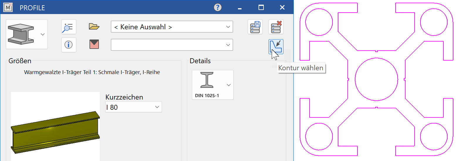
When the function is opened, the query Which model as profile cross section? appears. Now the 2D profile contour is selected in the drawing. With the next query Which reference point?, define the reference point of the cross-section to the longitudinal axis of the profile. Possible placements are the corner points and the cross-section centre. For the bill of material evaluation, all attributes from the 2D reference model are assigned to the object. Then the START POINT, the END POINT and the placement point (REFERENCE POINT) of the profile are queried.

The function is self-retaining and now allows the positioning of a further profile, whereby the START POINT, the END POINT and the placement point (REFERENCE POINT) of the profile are queried again. The function is ended by pressing the function button or by pressing the Esc key. A possibly incorrect 3D representation of the component indicates an open polygon of the selected 2D profile contour. Correct the 2D contour and the 3D depiction will be corrected.
Tip
If you have a large number of identical standard parts, we recommend the following:
Use the basic CAD function for copying standard parts. All standard parts are clearly identifiable as objects and can thus be manipulated as required with the cursor snap functions.
Various attributes are assigned to the object by the system for the bill of material evaluation. Before copying, check and complete all non-graphic information that you need for your bill of material by going to LAY OUT > ATTRIBUTES.
Model: Name of input dialog
Level: current is adopted
Class: current is adopted
Group: current is adopted
Material: Material from input dialog e.g.: St 37-2 (1.0037)
Standard: assigned e.g. DIN 1025
Designation: assigned e.g. I 200
When creating a free profile, the attributes of the 2D reference model, if any, are adopted.
The parameters for the depiction of the thread lines of the hidden lines and for the centre lines are defined by going to SETTINGS > OPTIONS > WORK PARAMETERS > MECHANICAL LINES.