Retaining rings
Retaining rings are machine components for the axial securing of components on shafts and in bores. The most common retaining rings used in mechanical engineering can be called up directly using their DIN standard and then inserted into the construction as ELITECAD objects.
Create retaining ring
|
|
Standard parts toolbar |
| ME-Objects menu > Standard parts > Retaining ring |
With a click on the function TOOLS > STANDARD PARTS > CREATE RETAINING RING in the toolbar or by selecting ME-OBJECTS > STANDARD PARTS > RETAINING RING in the menu bar, the settings of the last retaining ring drawn are active in the parameter window and the standard part can be set immediately.
Retaining rings property bar

The property bar is visible as soon as an existing retaining ring is selected for editing. Clicking on the retaining ring activates the property bar and the main values of the depiction of the retaining ring can be manipulated. Using the icon ![]() , the associated parameter window opens and all available values of the retaining ring can be modified.
, the associated parameter window opens and all available values of the retaining ring can be modified.
![]()
Retaining rings
| Image | DIN Standard | Range |
|---|---|---|
| DIN 471-1 Retaining rings for shafts - normal type and heavy type | Ring shaft Ø 3 to 300 | |
| DIN 471-2 Retaining rings (Circlips) for shafts - normal design and heavy design | Grooved shaft Ø 3 to 300 | |
| DIN 472-1 Retaining rings for bores - normal type and heavy type, ring | Ring shaft Ø 8 to 300 | |
| DIN 472-2 Retaining rings (Circlips) for bores - normal type and heavy type, grooved | Shaft Ø 8 to 300 | |
| DIN 6799-1 Retaining washers for shafts, washer | Shaft groove Ø 0.8 to 30 | |
| DIN 6799-2 Retaining washers for shafts, grooved | Shaft groove Ø 0.8 to 30 | |
| DIN 7993-1 Round wire snap rings and snap ring grooves for shafts and bores | Shaft Ø 4 to 125 | |
| DIN 7993-2 Round wire snap rings and snap ring grooves for shafts and bores | Shaft Ø 8 to 300 |
 Depiction (see General parameters)
Retaining ring parameters
![]()


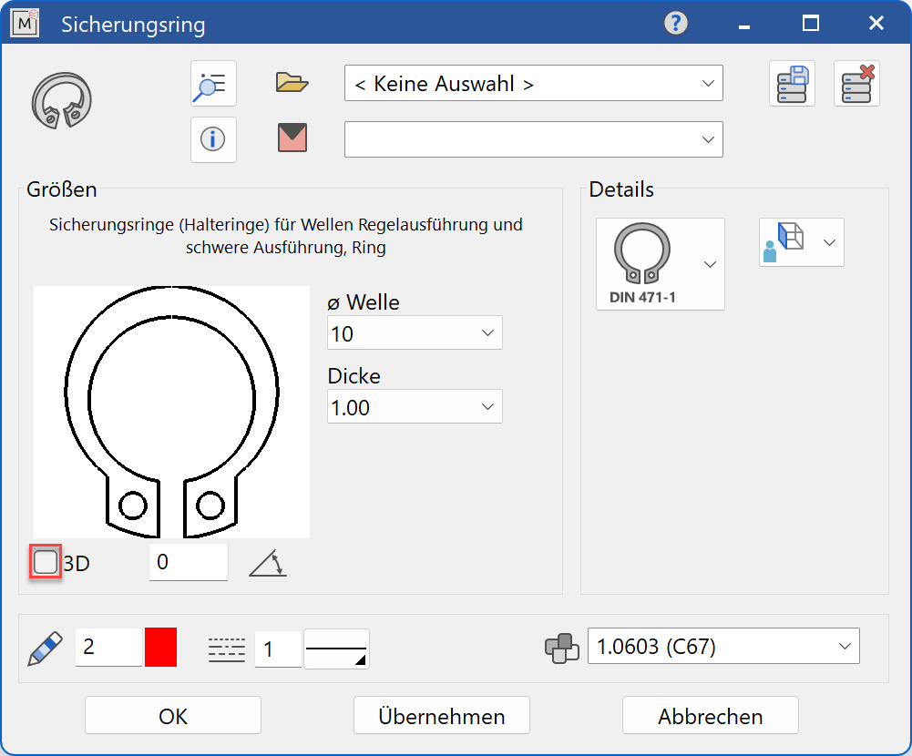
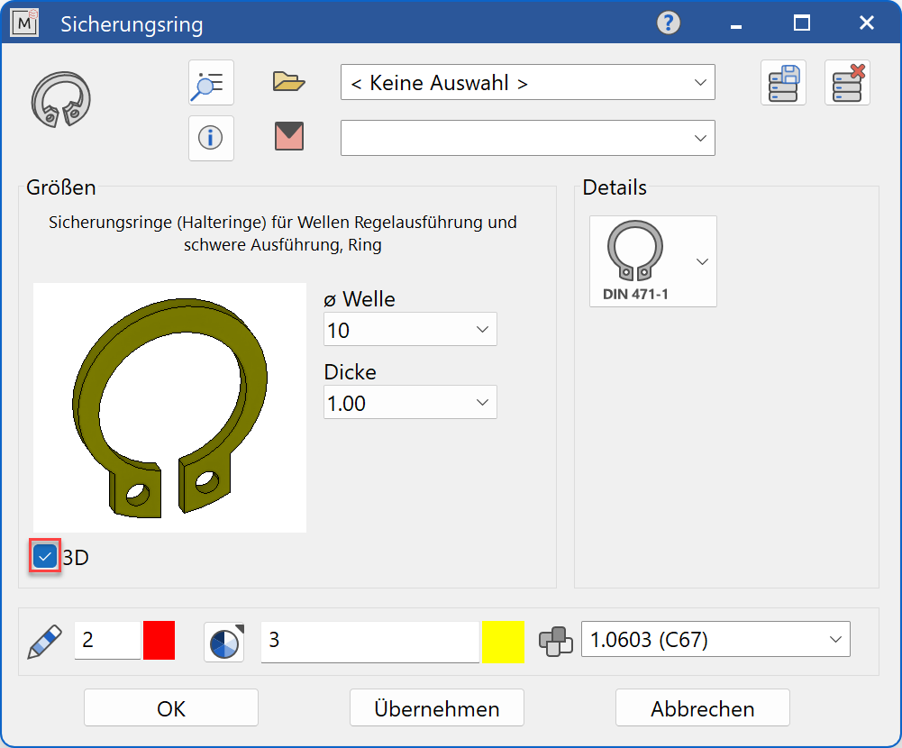
Decide whether the locking ring should be created in 2D or in 3D.
Tip
Specify the shaft diameter (bore) value first. With the selection of the thickness you choose between the standard version and the heavy version. The selection window will only offer dimensions that are available according to the selected standard.
The completed dialog is confirmed with  . This means that the retaining ring is dynamically active at the cursor for positioning in the drawing. The reference point is the intersection of the left contact surface of the retaining ring with the centre line of the retaining ring. The function is ended when it is positioned within the construction.
The function can be opened repeatedly for other retaining rings of the same type. The last input parameters are retained and are suggested the next time it is opened.
Display
Text field

Display of the standard designation of the standard part
Dimensions
Selection of the standard
Selection of the required standard from its respective group
Input values
The input fields available differ depending on the standard.
Shaft diameter

Shaft diameter for the retaining ring in standard increments
Shaft groove diameter

Shaft groove diameter for the retaining ring in standard increments
Bore diameter

Bore diameter for the retaining ring (groove) in standard increments
Thickness

Thickness of the retaining ring in standard increments
Shape type

Execution of the retaining rings/grooves according to the desired shape type.
Orientation angle
Angle position of the retaining ring relative to the X-axis in the 2D representation