Screwings
A screwing is a combination of connecting elements (standard parts) in order to create a releasable connection of compatible parts with one another. The geometry of the screwing is checked by ELITECAD. If, for example, the max. length from the selected screw standard is too short for the specified clamping length, the error message Clamping length is greater than max. clamping length will be displayed.
The message Diameter is not included in the standard indicates individual parts of the screw connection which, according to the relevant standard, are not available for the specified screw diameter.
Due to the multitude of possible solutions, the correction to a technically possible connection is the responsibility of the designer. Also check the design of the screwing in the preview window of the input dialog. This graphical preview is true to scale and may show inconsistencies in the parameter input. For example, if the length specification of a threaded blind hole or similar is too short, it can be noticed and corrected.
The division point between the components to be connected is calculated automatically from the sample structure (object structure). It is therefore essential for the correct execution of the function that the components are available as separate models (objects). Incorrect representations of the screwing resulting from errors in the model structure can also be seen in the preview window.
Create screwing
|
|
Standard parts toolbar |
| ME-Objects menu > Standard parts > Screwing |
ELITECAD combines individual parts such as screws, washers and bores into meaningful screwings selected individually by the designer. With a click on the function TOOLS > STANDARD PARTS > CREATE SCREWING in the toolbar or by selecting ME-OBJECTS > STANDARD PARTS > SCREWING in the menu bar, the settings of the last screwing drawn are active in the parameter window and the screwing can be set immediately.
Screwings property bar

The property bar is visible as soon as an existing screwing is selected for editing. Clicking on the screwing activates the property bar. Using the Icon ![]() , the associated parameter window opens and all available values of the screwing can be modified.
, the associated parameter window opens and all available values of the screwing can be modified.
| Function | Description |
|---|---|
| Screwing parameters | |
 |
Depiction (see General parameters) |
Screwing parameters
![]()
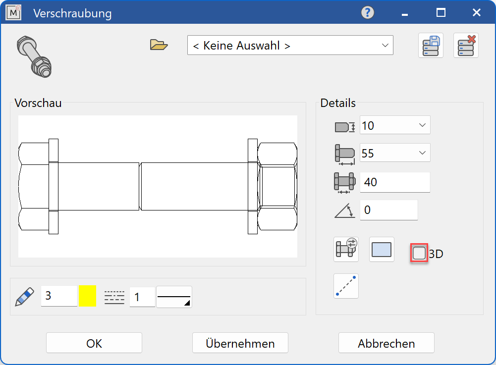
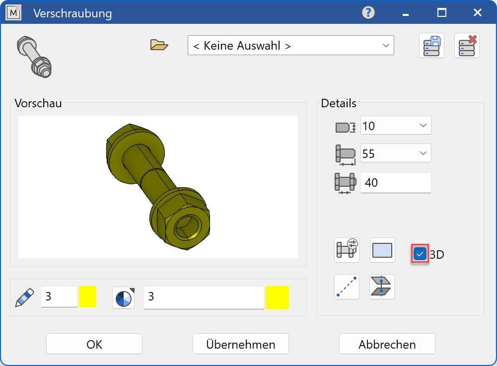
Decide whether the screwing should be created in 2D or in 3D.
Tip
Specify the thread diameter value first and then follow the following procedure:
- For the 3D working plane, select the head side (it is screwed in the z-direction).
- Open up the screwing parameters dialog.
- Select 2D or 3D representation.
 Select the individual parts of the screwing.
- Select either
 point input or
  area input.
  Update and review the preview
- Create the screwing with
 or
or  .
.
The function is ended when it is positioned within the construction. The function can be opened repeatedly for further screwings of the same type. The last input parameters are retained and are suggested the next time it is opened.
Dimensions
![]() Settings for screwing
Settings for screwing

In the selection dialog Screwing settings, a screwing containing up to 9 different standard parts can be created. The countersink and drilling are also generated according to DIN. Behind every single button there is a pull-down menu with the available standards for the corresponding individual part.
![]()
Selection of the desired screw for the screwing
The material for the screw is set in the main screen. In the DIN 7990 and DIN 7968 standards, the nuts are specified in accordance with the standard.
![]()
Selection of the desired washer for the screwing
The material for the washer is set in the dropdown menu below the washer. It is also possible to set no washer.
![]()
Selection of the desired washer for the screwing
The material for the washer is set in the dropdown menu below the washer. It is also possible to set no washer.
![]()
Selection of the bore for the screwing in the first plate
In the dropdown menu below the hole, the execution quality is set according to the standard (fine, medium, coarse).
![]()
If you select "no bore", only the screwing is shown without any parts to be connected.
![]()
Selection of the countersink for the screwing in the first plate
In the dropdown menu below the countersink, the row (socket, ring spanner, countersink) is set and the depth of the countersink is specified. The depth of the countersink is automatically calculated by ELITECAD when defining the screw length.
![]()
Selection of the bore for the screwing in the last plate
In the dropdown menu below the bore, the execution quality is set according to the standard (fine, medium, coarse).
![]()
Selection of the bore for the screwing in the last plate with thread
![]()
Selection of the bore for the screwing in the last plate as a threaded blind hole
The thread length in the blind hole is set in the dropdown menu below the blind hole. Threaded blind holes with thread run-out standard, short and long as well as thread undercut standard and short are available for 2D and threaded blind holes with thread run-out standard for 3D.
With the selection of threaded blind hole, the buttons for the nut-side standard part selection are automatically hidden.
![]()
Selection of the desired washer for the screwing
The material for the washer is set in the dropdown menu below the washer. It is also possible to set no washer.
![]()
Selection of the desired washer for the screwing
The material for the washer is set in the dropdown menu below the washer. It is also possible to set no washer.
![]()
Selection of the desired nut for the screwing
The material for the nut is set in the dropdown menu below the washer. It is also possible to set no nut.
![]()
Selection of the desired nut for the screwing
The material for the nut is set in the dropdown menu below the washer. It is also possible to set no nut.
Input values
The input fields available differ depending on the standard.
Thread diameter
![]()
Thread diameter of the screwing in standard increments
Only the values permitted for the selected thread diameter are offered in the screwing settings.
Length of screw
![]()
Length of the screw in standard increments
Clamping length
![]()
Clamping length of the screw connection
Clamping length by 2 points (point query 2D)
![]()
The first point defines the HEAD SIDE and the second point the NUT SIDE of the screwing. By entering both points, the position of the screwing and the necessary screw length are automatically determined.
- HEAD SIDE? Specify the insertion point as the element point of the first plate.
- at the through hole: NUT SIDE? select the normal element point of the last plate
or
- for threaded blind holes: SCREW DEPTH? Information about a point that is inside the last plate.
Clamping length by 2 points (point query 3D)
![]()
The first point defines the HEAD SIDE and the second point the NUT SIDE of the screwing. By entering both points, the position of the screwing and the necessary screw length are automatically determined.
- HEAD SIDE? Specify the insertion point on the first plate.
- at the through hole: NUT SIDE? Specify the point at the bottom of the last plate. Only the z-value is used
or
- for threaded blind holes: SCREW DEPTH? Information about a point that lies inside the 2nd plate. Either using snap mode point or direct entry using the keyboard (e.g. ,, - 50). Only the z-value is used.
Clamping length over 2 surfaces (only 3D)
![]()
The first surface defines the HEAD SIDE and the second surface defines the NUT SIDE of the screwing. When you enter both surfaces, the necessary screw length is automatically determined. Then the screwing position is entered.
- FIRST SURFACE? Specify the surface on the first plate
- at the through hole: SECOND SURFACE? Specify the surface on the last plate
or
- for the threaded blind hole: SCREW DEPTH? Information about a point that lies inside the 2nd plate. Either using snap mode point or direct entry using the keyboard (e.g. ,, - 50). Only the z-value is used.
- POSITION WHERE TO? This indicates the position of the screwing on the head side.
Create preview
![]()
The preview window will be updated according to the selected parameter settings.
Save screwing
Give the screwing a name and save this setting. It can be called up at any later point in time and used with all available values for screw diameter and clamping length for quick screwings.
![]()
These predefined screwings are updated automatically after selecting the appropriate name in the name list. For the entry of new and the modification of existing screwings in the record-table, the SAVE RECORD function is used.
![]() DELETE RECORD
DELETE RECORD
This menu item is used to delete a record that is no longer required.
Use this option and define your frequently used screwing combinations such as:
Standard through screw connection
Screw-in fitting with threaded through hole
Screw-in screw connection with threaded blind hole, etc
Modify screwing
Borings and countersinks cannot be previewed in 3D.
In order to enable a accurate preview, it is essential that you first define the components to be connected by specifying the two limit points of the clamping length. This automatically identifies the corresponding objects for the assignment of the drilling elements and for correcting the visibility, additionally the required screw length can be determined.