Coordinate systems
Define coordinate system
|
|
Settings toolbar |
| Image properties |
Improved · 17 R1 · Improvements
The coordinate system can be rotated via an angle or point entry or by using the handles. All inputs and manipulations (e.g. vertical or horizontal) will then refer to the new coordinate system.
The new entry generates a symbol on the screen. Double-clicking a coordinate symbol switches to that coordinate system. Double-clicking the main coordinate symbol in the lower left corner switches back to the original work plane.
If custom coordinate systems have been saved with the drawing, they are automatically displayed when it is loaded.
| Origin | Coordinate system rotated |
|---|---|
 |
 |
Tip
A coordinate symbol can be selected and deleted.
Coordinate system property bar
New · 17 R1 · Improvements

The property bar is visible as soon as an existing coordinate system is edited.
You can manipulate the main values in the coordinate system's property bar.
| Function | Description |
|---|---|
| Activate coordinate system | |
 |
Coordinates of the origin |
| Rotation angle |
Activate coordinate system
![]()
This button activates the currently edited coordinate system.
To deactivate it, activate a different coordinate system or reset the work plane from the image properties. ![]()
Origin coordinates
The position of the origin relative to the current work plane can be entered in the input fields X and Y.
Rotation angle
![]()
In this field, the angle of rotation relative to the starting position (work plane) can be entered.
Reference point general
The reference point is used for working with georeferenced data.
The reference point is a special rotated coordinate system and has an additional offset relative to a georeferenced coordinate system.
If the reference point is active, the measured coordinates are shown relative to the georeferenced origin, i.e. the offset is added.
The reference point is also used to display the coordinates of a terrain including the offset.
There can only be exactly one reference point in a drawing. Different data can be aligned with each other using this point.
This happens automatically when drawings are combined and if a reference point exists in the active and loaded drawing.
Data from external formats is also loaded georeferenced or a reference point is created if one does not already exist (e.g. for terrain data, point clouds, IFC, etc.)
Reference point
|
|
Settings toolbar |
| Settings menu > Reference point… |
The function is used to relocate the default origin (centre of screen)
- X-, Y-coordinates of the new reference point
- Rotation of coordinate system
- Reposition Drawing
From now on, the X- and Y-coordinates of all other points you define will be based on the new reference point.
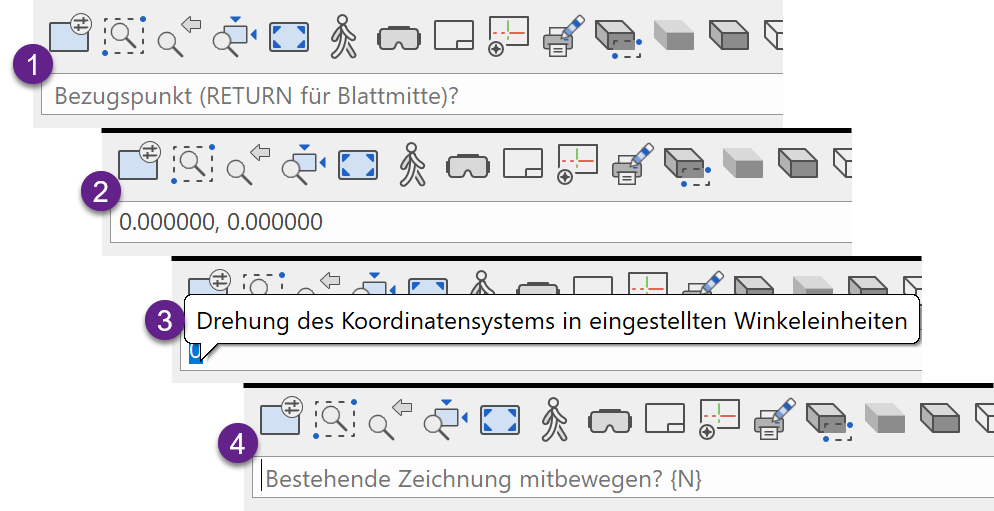
Query function
Reference point ( Enter for centre of page)
Specifying point by clicking on screen (1)
X-,Y-coordinates for this point
By default, the reference point has the coordinates of (X = 0, Y = 0). You may also assign specific coordinates to it, e.g. (X = 10000, Y = 15000). (2)
By default, the rotation is 0 degrees (or radian). However, you may also enter another angle in order to take into account the difference between north and the verticals for surveying. (3)
Move active drawing as well?
By default, the drawing is not moved as well. In other words, existing objects remain at the same position on the screen. However, the INFORMATION > COORDINATES OF POINT function will display other coordinates after you change the reference point.
If you respond to this query (4) with "Y", the contents of the screen will be moved to a new screen position so that the INFORMATION > COORDINATES OF POINT feature will still display the same coordinates as before after the change in reference point. This option is especially significant for surveying.
- enter the X, Y coordinates points.
- Pressing Enter will automatically fill in 0,0. Press +enter++ again to confirm the entry.
- Rotation is entered by degrees (or other angle unit if set in the options menu). Confirm with Enter.
- Confirm with Y or N and Enter
Reference point property bar
New · 17 R1 · Improvements

The property bar is visible as soon as the reference point is edited.
You can manipulate the main values in the reference point's property bar.
| Function | Description |
|---|---|
| Coordinate system symbol | |
| Activate coordinate system | |
 |
Coordinates of the origin |
| Rotation angle | |
| Offset of the origin |
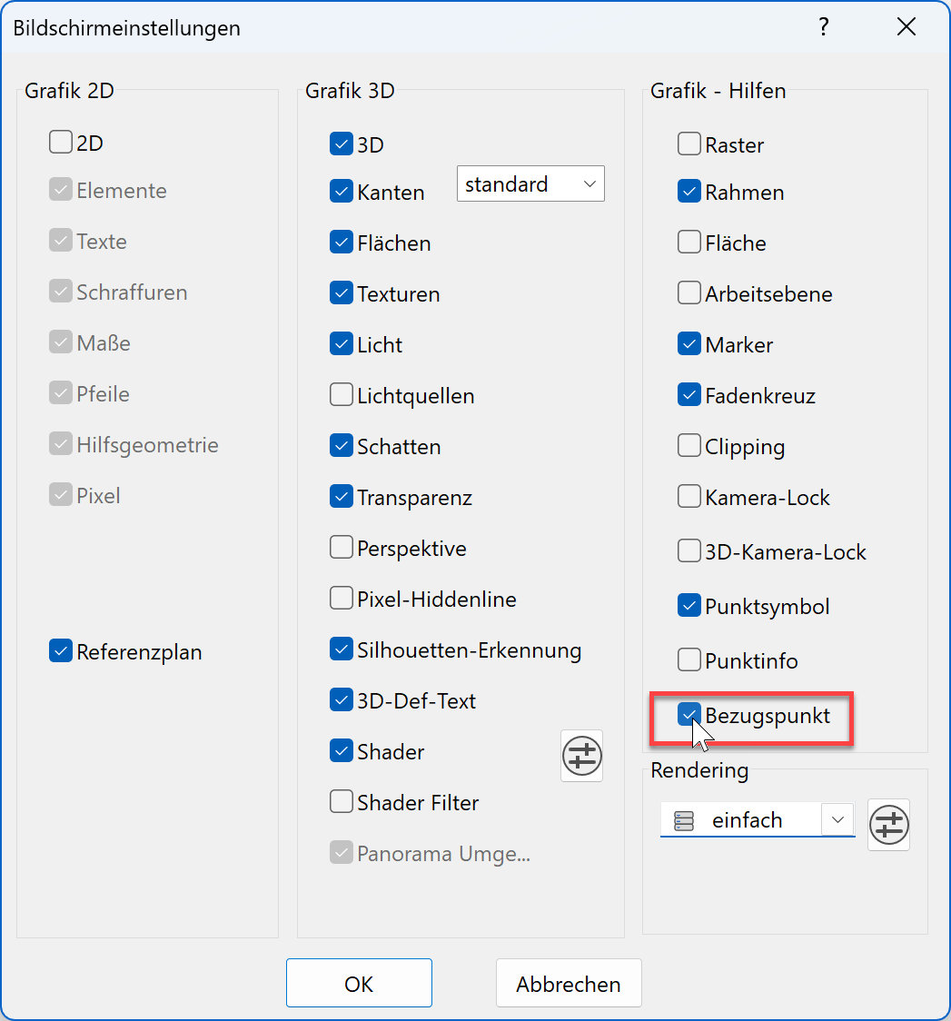
Georeferenced coordinate system symbol on/off
![]()
Switch the georeferencing coordinate symbol on and off.
Tip
The georeferencing coordinate symbol can also be activated-deactivated from the screen settings menu.
Origin offset
![]()
![]()
In the input fields X and Y the offset of the origin relative to a georeferenced origin can be entered.
This option is not available for user-defined rotated coordinate systems, but only for the CAD reference point.
Tip
The reference point and the coordinate system symbols, with their red X-arrows and green Y-arrows, look very similar. They differ at the point where they intersect. In a coordinate system, the X-arrow is placed on the Y-arrow, whereas with the reference point, a yellow rectangle appears at the intersection.
| coordinate system | reference point |
|---|---|
 |
 |