Create Terrain
|
|
Terrain toolbar (AR) / Extras (ME) |
| Extras menu > Terrain (AR) / Extras menu > Special functions > Terrain (ME) |
Click the TERRAIN function to start a terrain model. The terrain property bar appears and an empty terrain object is created. All further data is automatically inserted into this object.
Terrain property bar

The property bar becomes visible if you select the TERRAIN function to generate a terrain or if you click an existing terrain to edit it.
Terrain options
![]()
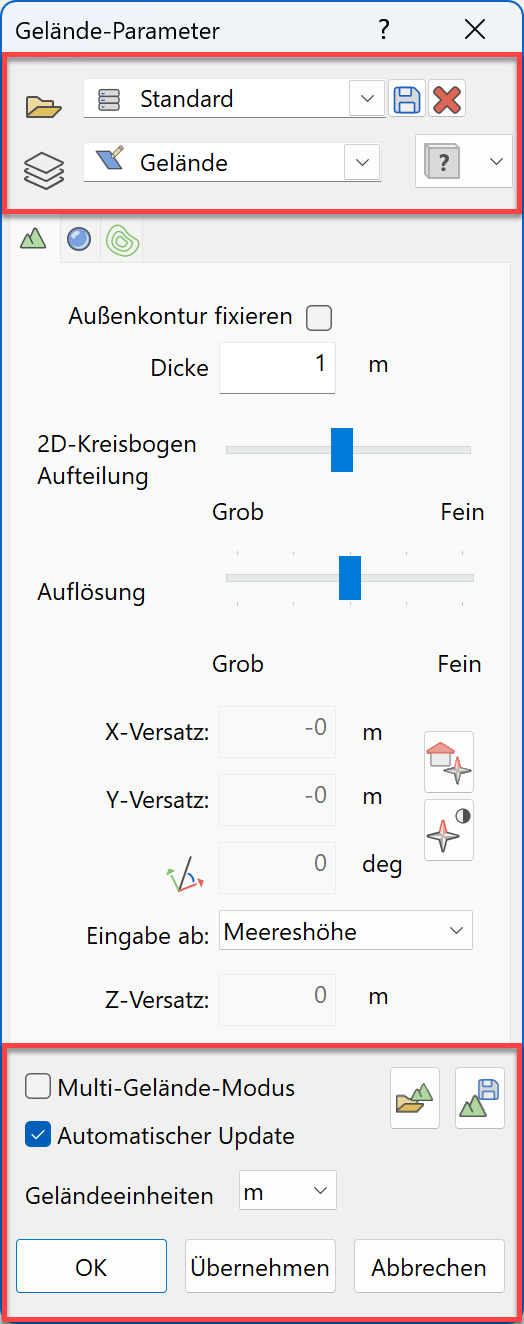
The "Parameter(s)" function calls up the detailed terrain options.
All parameters relevant to generating a terrain are saved with the terrain object. If you load a drawing with terrain, these are adopted and applied to the active parameters.
General parameters
Type
![]()
Used to select predefined parameters.
In order to save a new terrain type record, the parameters have to be set and a new name has to be entered into the text field.
![]() Saving a terrain type record
Saving a terrain type record
![]() Deleting a terrain type record
Deleting a terrain type record
Layer
![]()
Every construction part has the layer field in the record with the layer selection. It is then guaranteed that the construction parts already lie in the correct layer when they are generated.
You can create a new layer by entering its name into the text field.
Renovation planning state
![]()
This option is only available in ELITECAD Architecture and is described in chapter Renovation planning state.
The state is valid for the whole object and is not for individual terrain modifications.
Multi-terrain-mode
If this mode is switched ON, a new terrain is generated whenever a terrain function is activated. If the mode is switched OFF, an existing terrain is loaded for edit operations, and only if there is no existing terrain in the drawing a new terrain will be created.
When multi-terrain mode is enabled, the activation of terrain functions behaves like the functions of other objects – at the beginning a new object is created, and upon selection, the existing object is manipulated.
If the user only wants to use a single terrain model, the mode can remain switched off. The terrain function looks for the terrain model and activates it for modification.
Automatic update
If this is switched on, any modifications made to the terrain are implemented immediately.
Some actions, however, require manual recalculation.
For performance reasons, this switch can be switched off. You can then only initiate a calculation by selecting the GENERIEREN function.
Terrain units
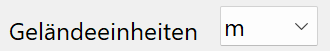
The unit is used to show and enter height values. It is also used for labelling height lines, displaying terrain point coordinates and showing the volume difference.
Import terrain
![]()
This function loads a terrain from a file as a reference terrain.
Further details about importing can be found in the Import terrain chapter.
Export terrain
New · 17 R1 · Improvements
![]()
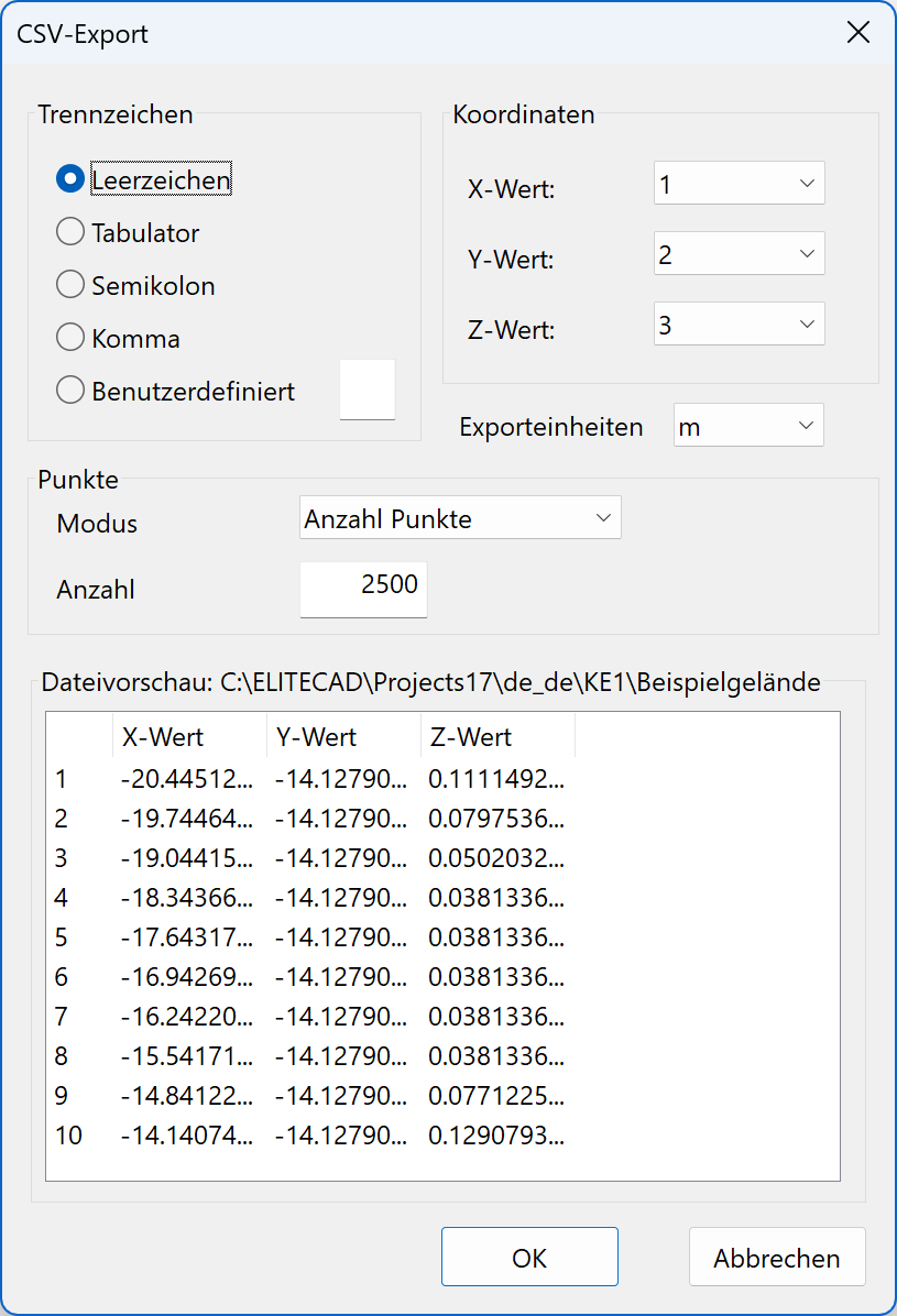
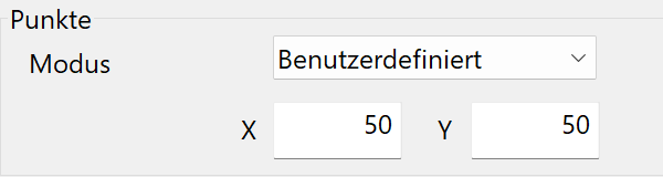
The selected terrain can be exported for use in another model or program. When exporting, points of the terrain surface are written to an ASCII text file.
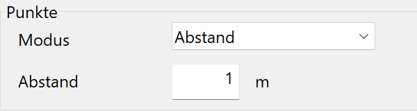
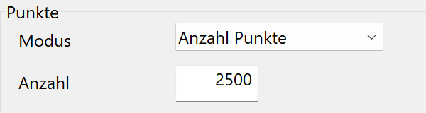
When exporting, points are placed on a rectangular grid. There are three options for the method of distribution: the distance between points, the total number of points or a user-defined number in the X and Y direction.
Generation parameters
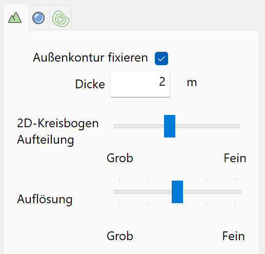
Fix perimeter contour
Once the reference terrain is saved and this option is activated, the height along the perimeter contour is no longer modified.
Thickness
The terrain is represented as a volume object and also has a surface on its underside. The height of the underside must be specified. The thickness indicates how far the underside should be away from the lowest point of the top surface.
2D-arc segmentation
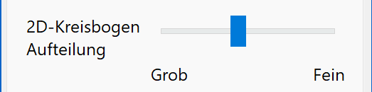
This affects the drawn contours of the street, excavation, etc. If needed, existing arcs are replaced by one or more lines, depending on the setting.
Resolution
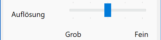
The calculated surface's precision can vary. Even the "low" selection requires a certain minimum amount of precision.
Georeferencing
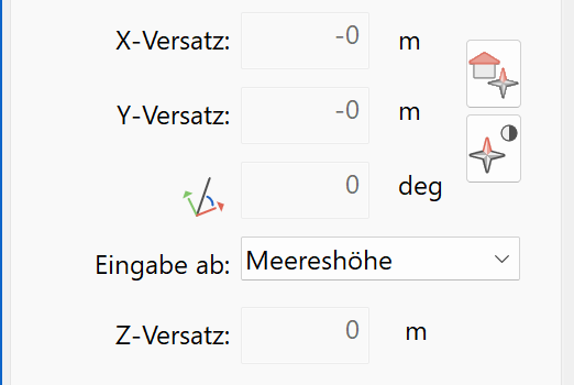
X/Y-offset
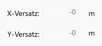
The X/Y shift of the reference point is read in this field. This is only for information and can not be edited here. The terrain origin is the CAD reference point and applies to all terrain objects in the drawing.
Explanation
An imported terrain is always loaded georeferenced, i.e. relative to the CAD reference point. If there is no CAD reference point yet, the terrain is loaded centered in the middle of the page and the CAD reference point is created. To ensure that the height points still show the original XY coordinates when selected, the corresponding offset is added to the coordinates. Should the need arise to manually define the offset, this is done from the Settings menu/Reference point…
Rotation
![]()
As is the case with the X/Y offest, this is only here for information and can be defined using the CAD reference point Settings menu/Reference point…
Activate georeferenced coordinate system
New · 17 R1 · Improvements · Highlight video
![]()
The terrain origin is always the CAD reference point. The terrain origin is valid for all terrain objects and serves as a reference point for the coordinate display of terrain points and curves. This also applies if the CAD reference point is not activated.
In order to display coordinates for points of the model georeferenced, the reference point for measuring must be set to the terrain origin.
This function activates the CAD reference point as the active coordinate system. This reference system also differs visually from other rotated coordinate systems by a yellow rectangle. If this reference system is enabled, the coordinates of the entire model are georeferenced in the same way as the coordinates of the terrain points. Using the function RESET WORKPLANE, the reference system can be set to centre of the page.
The CAD reference point can also be activated by double-clicking on the symbol.
Georeferenced coordinate system symbol on/off
New · 17 R1 · Improvements
![]()
Switch the georeferencing coordinate symbol on and off.

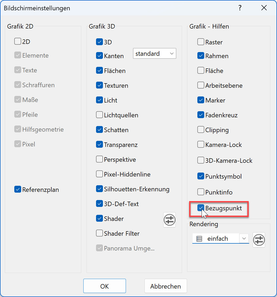
Tip
The georeferencing coordinate symbol can also be activated-deactivated from the screen settings menu.
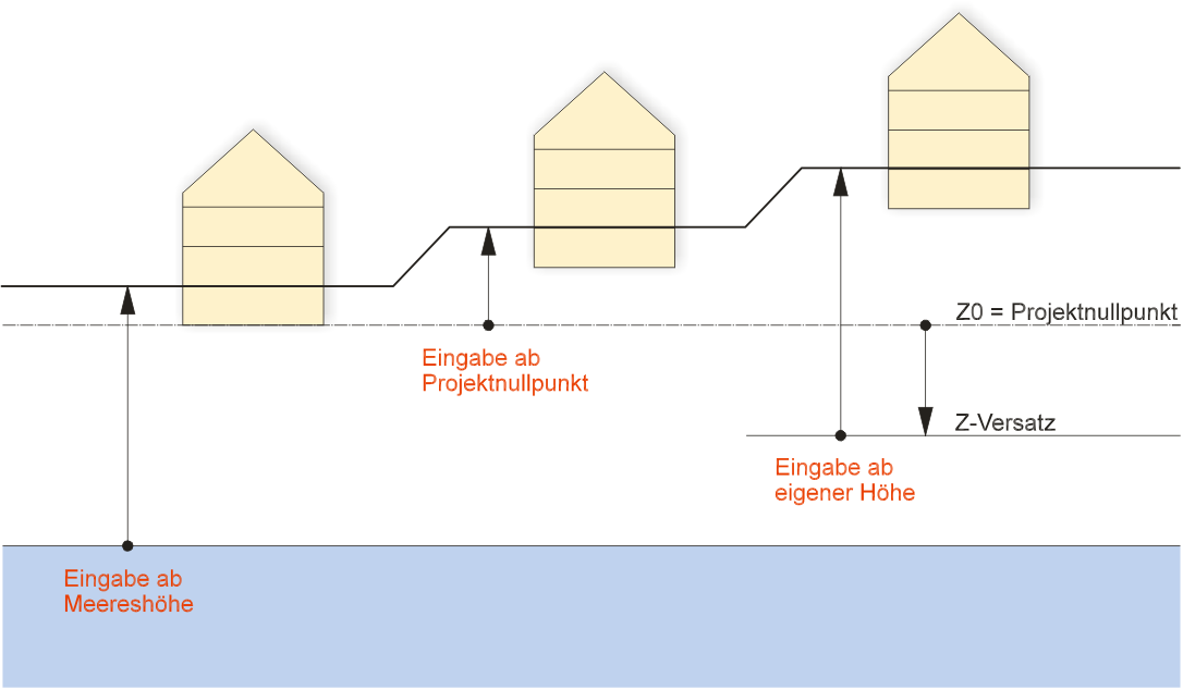
Entry from
Different options for entering the heights can be selected here. References to buildings and project settings are only valid for ELITECAD Architecture.
The terrain's default Z-height is always zero. The effect this null point has on the structure is dependent on the structure settings. If, for example, the "sea level" or "per structure" height marking system is selected here, the first entered structure is always at the null Z-height, so equal to the terrain's null point regardless of its height situation. If the "project null" height marking system is chosen, the project's null point is at the height entered here.
If the terrain's entry height is modified after its creation, do not correct the terrain's height itself but the values of the height curves, height lines, excavation, label, etc. If you would like to move the terrain's height, you must use the MOVE POINTS AND CURVES IN Z-DIRECTION function.
Manually set height
This switch setting unlocks the Z-OFFSET field in which a particular value can be added. If, for example, you select 20 m as the offset and define the heights with 20 m, the points are at the null Z-height.
Project null
This option automatically sets the "Z-offset" to 0 and the height entries are entered from the project null point. If the heights are defined with a 0 value, the points are at the null Z-height.
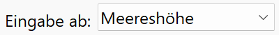
Sea level
If the SEA LEVEL option is selected, the height situation of the first entered structure is shown. Always indicate the heights in real sea levels.
Offset
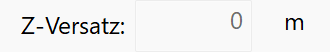
The Z-offset is either entered or read in this field.
Adjust terrain horizontally
If a terrain model is adjusted relative to another object using the manipulation functions, it does not affect the terrain origin. On the other hand, if all terrain models in a drawing are moved horizontally, the terrain origin is adjusted as well. This allows for horizontal adjustments of an imported terrain to be made so it can be better aligned to the model without altering the georeferencing.
Adjust terrain in height
When a terrain object is adjusted in the z-direction using the manipulation functions, the 2D data of the terrain object will remain in the work plane at a height of zero. In contrast to the MOVE POINTS AND CURVES IN Z-DIRECTION function of the terrain property bar, the “normal” adjustment of the terrain will also move the terrain modifications (excavation, etc.). That way it is now also possible to correctly adjust terrain objects in the height direction.
Surface parameters
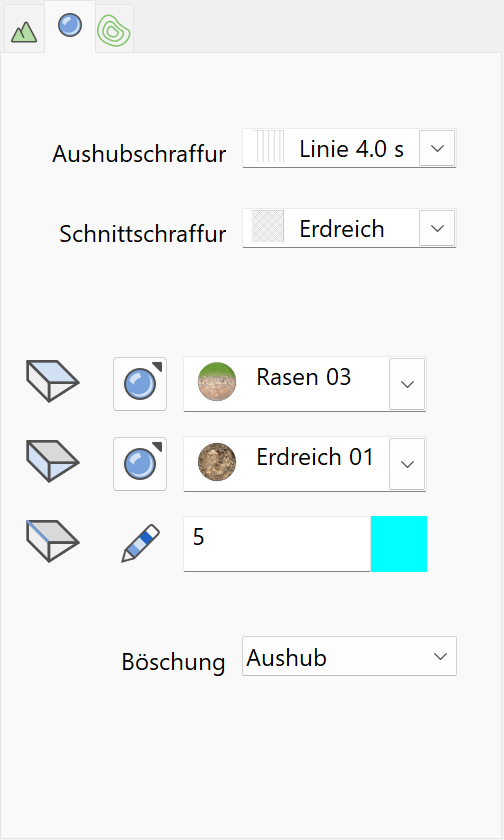
Excavation hatch
This is used for representing the slopes in an excavation plan.
The type of hatch can be selected from the "selection box" where all records saved under the hatching parameters are listed.
Tip
All line hatches are always automatically shown perpendicular to the excavation edges regardless of the angle with which they were saved. Cross hatches are also represented with only one line.
Section hatch
This is used while creating a section view in order to hatch a section of the terrain. The type of hatch can be selected from the "selection box" where all records saved under the hatching parameters are listed.
Colour/Visualisation material for surfaces and sides
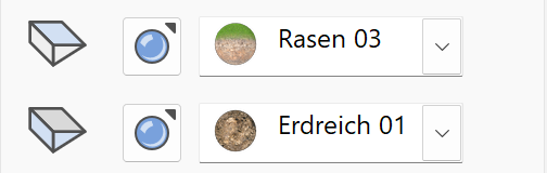
Colour mode/Visualisation material mode
![]()
![]()
This switch allows you to toggle between colour mode and visualisation material mode. For more details, see the Colours and Visualisation materials chapters.
Edge colour

Slope
New · 17 R1 · Improvements
Choose whether hatches for all slopes (e.g. deposit, roads) are shown or only those of excavations.
Height line parameters
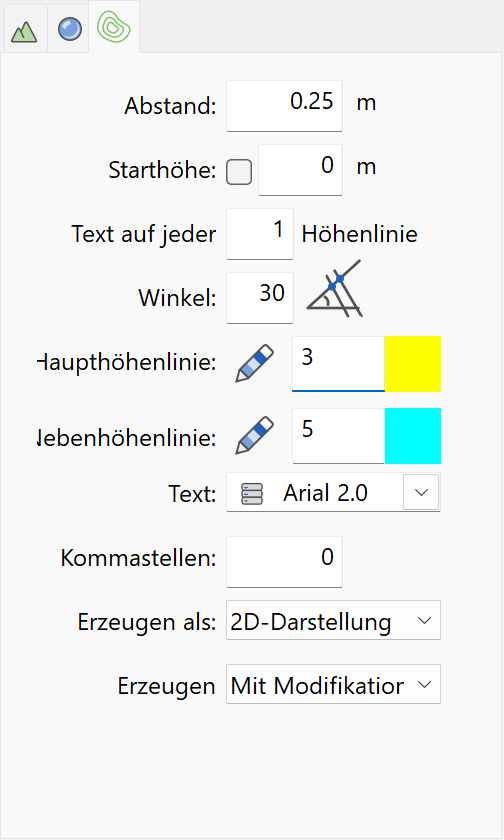
Distance
This entry determines the height distance with which the height lines will be drawn.
Start height
The height lines are displayed and labelled from this height.
Height line text
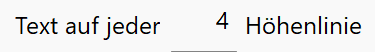
You can indicate here on which height line the text should be. The first pen from the Colour selections is used for the text on the labelled lines.
Angle
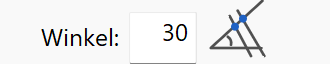
The angle indicates an approximate guideline for the text position.
Colour selections

The first pen applies to the labelled height lines and the second pen for the height lines in between.
The pen colours can be directly entered or selected from the colour table. (from 0-1023)
Text parameters

The type of text can be selected from the "selection box" where all records saved under the text parameters are listed.
Decimal places
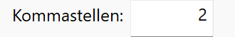
Enter how many digits there will be after the decimal point.
Create as
Improved · 17 R1 · Improvements
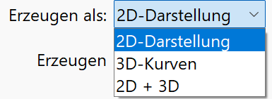
Enter whether the height lines will be generated in the floor plan, in their actual height or in both 2D and 3D.
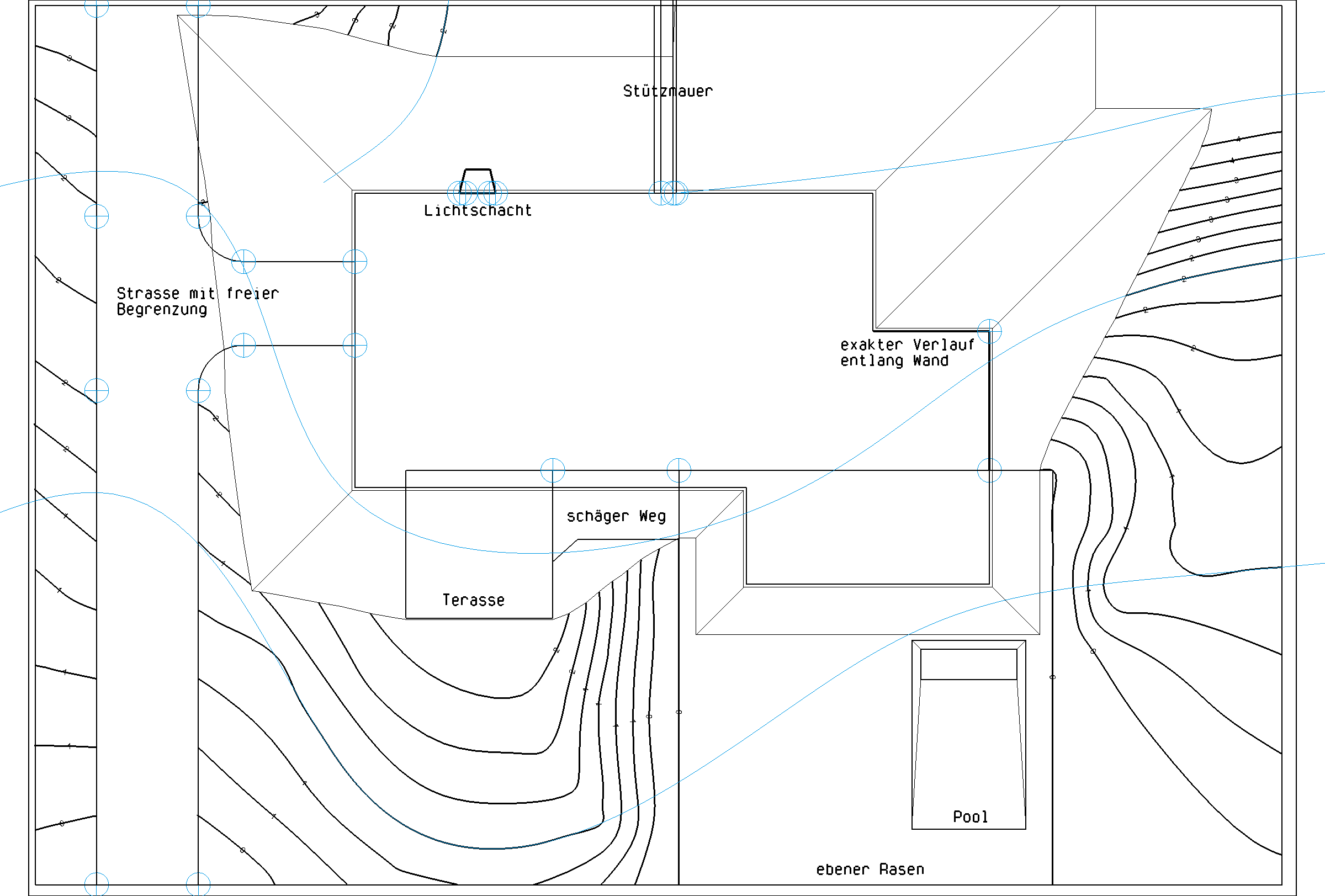
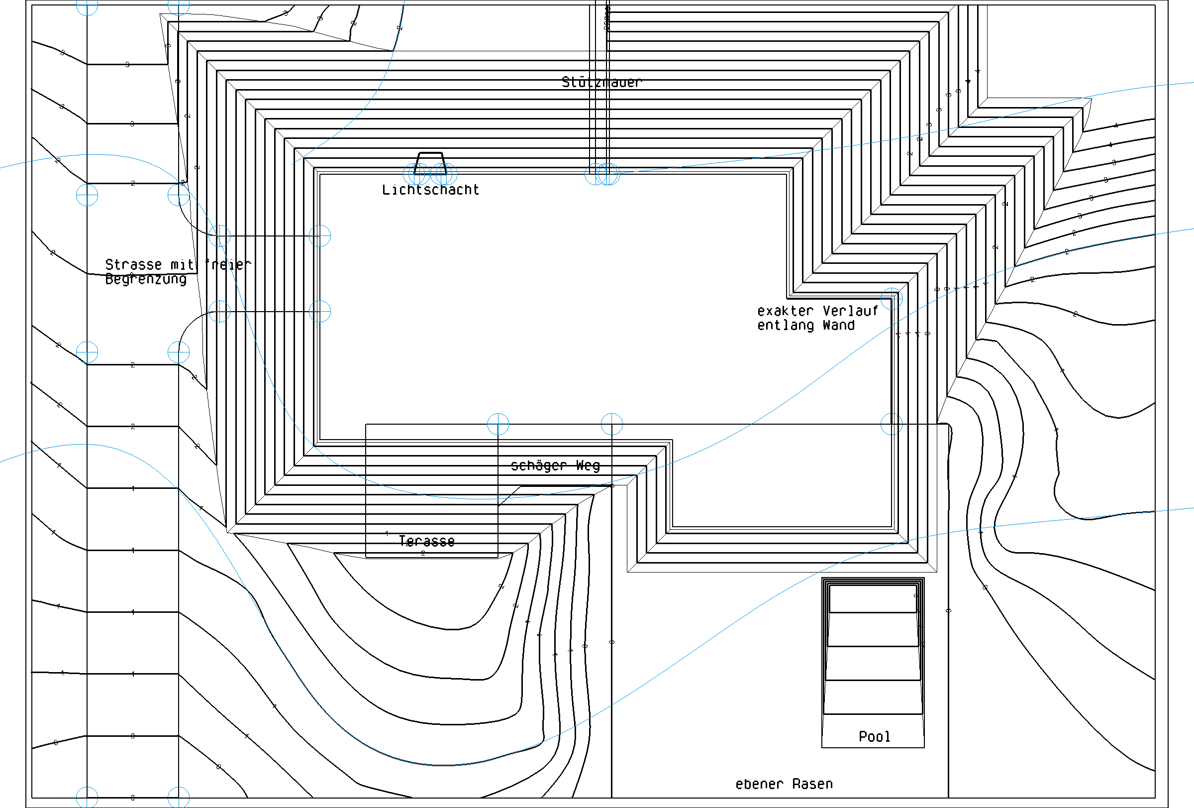
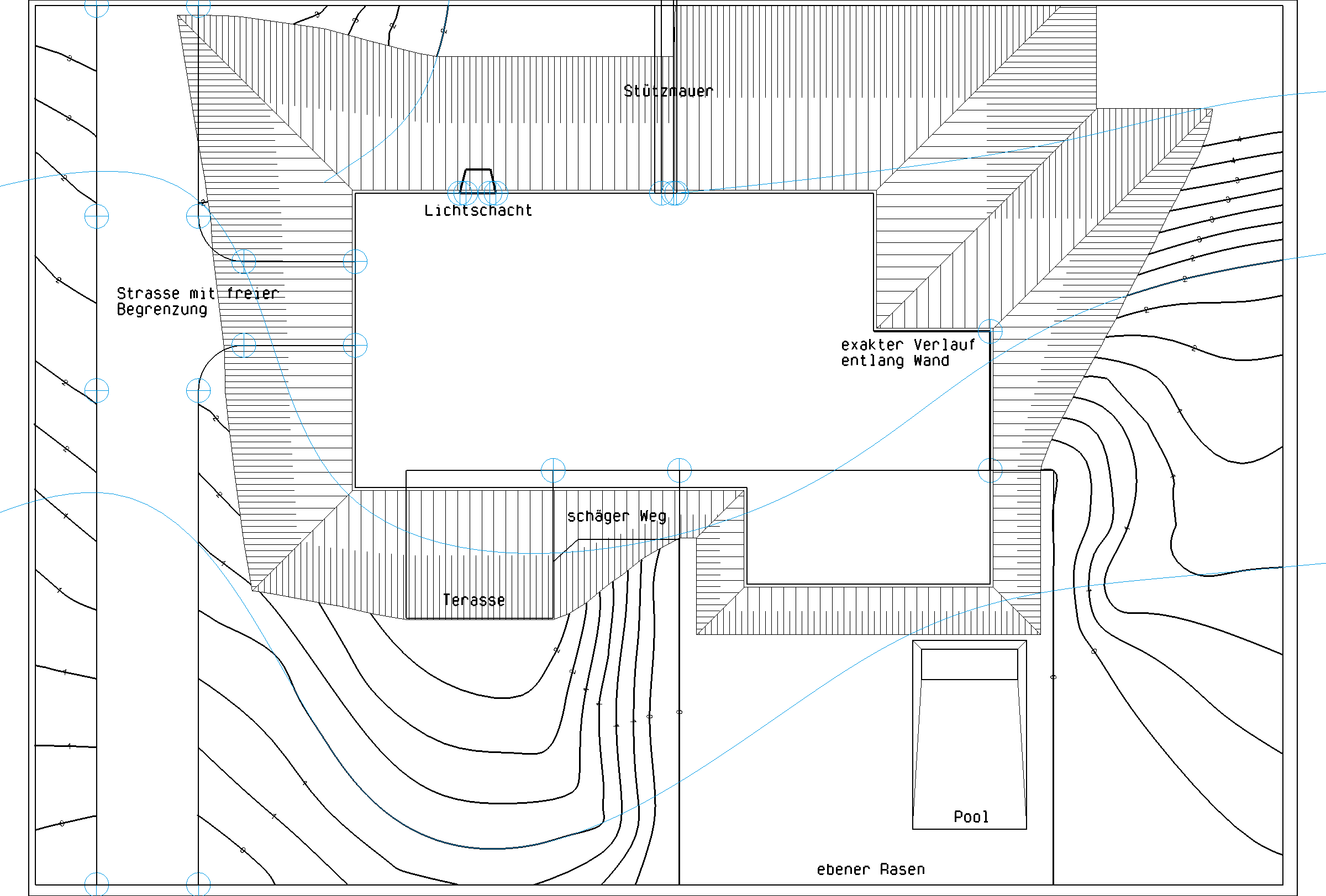
Create
New · 17 R1 · Improvements
Choose whether the height lines should be shown also for modifications.
Tip
When it is being depicted with modifications the *Slope Hatching* still takes precedence if it is activated.
| Without | With | |
|---|---|---|
Deactivated |
 |
 |
 Activated |
 |
 |
Generate
![]()
The terrain is recalculated using the "Generate" function. All definition curves and definition points are used. In case a perimeter contour was defined, the terrain is restricted by this contour.
Note
New · 17 R1 · Improvements
In case the Gerneration calculation is too large and taking too long to calculate, the process can be aborted with Esc.
Terrain view mode
New · 17 R1 · Improvements

With structure
![]()
Edits are generally carried out in this depiction mode. The terrain is displayed depending on the screen parameters.
Step by step
New · 17 R1 · Improvements · Highlight video
![]()
This opens the terrain inspector which allows each action in the development of the terrain to be viewed individually.
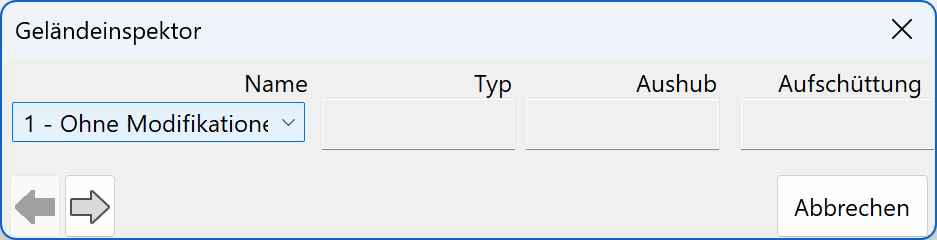
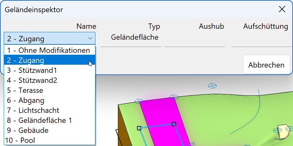
Tip
All modifications are given a name automatically. The automatic naming consists of the type of modification it is and a number. Terrain surface 1 is an example from the above image.
These can of course be edited at anytime to suit any specific needs.
Example from above image: Terrain surface 1
Reference terrain
![]()
This switchs to the reference terrain. Should this not be present, the terrain is displayed without architectural measures. In this case, a warning message appears.
Excavation mode
Improved · 17 R1 · Improvements

Without excavation
![]()
Edits are generally carried out in this mode. The excavation contours are integrated perpendicularly upwards and without side distance into the terrain. The final edited terrain then directly connects to the building.
With excavation
![]()
The terrain is represented as a 3D excavation plan with all slopes in this depiction mode. The terrain is recalculated when toggling between depiction modes.
Colour mode/Visualisation material mode
![]()
![]()
This switch allows you to toggle between colour mode and material mode. For more details, see the Colours and Visualisation materials chapters.
Entry
Entry mode
You have two options available for generating a terrain edge/area, perimeter contour, excavation, landfill/dispersal, street or path: Either draw the contour directly, or you can define a polygon before accessing the function and select it.
Draw contour manually
![]()
You can draw a contour directly.
Create from existing contour
![]()
You can select an existing 2D polygon.
Switch on height lines
![]()
Height sections can be activated in the property bar using this switch. Planar, horizontal sections are calculated and the result is projected as 2D curves into the X/Y-plane. The calculation follows according to the set parameters with distance and label. These curves serve as a result for the excavation plan and are not provided for modifying the terrain.
Switch on slope
![]()
Slope hatches can be activated in the property bar using this switch. The outlines of the excavation contour's slopes are hatched according to the selected parameters. If the hatch in use is a line hatch, then the lines point in the direction of the steepest incline.
Reference terrain and volume

![]()
If no reference terrain exists, the excavation volume is determined as follows:
The terrain surface is generated from definition curves and points. This state is adopted as its initial state. Excavation, landfill/dispersal, streets, etc. are integrated into the surface and result in a new edited surface. The difference between the initial state and the edited surface is displayed as volume in the property bar.
Note
A positive value means: material must be added; negative means: material must be removed.
In practice, the terrain appears different on an undeveloped parcel of land as it should finally look. Height points are generally determined by the surveyor and describe an original terrain. The volume difference should optionally refer to the original terrain. In order to reach this, you must first define the original terrain and then freeze this state using the "Save reference terrain" function. This frozen terrain is referred to as reference terrain. Points and curves can later be modified in such a way that the final surface is created. If the reference terrain has been created once, the calculation of the volume difference refers to the difference between the reference terrain and the finished, edited surface.
The reference terrain can no longer be edited but can be replaced by recreating another. If the perimeter contour is modified, then the reference terrain should be reset since the difference would not give a meaningful value.
When saving the reference terrain, you can choose whether the reference terrain is saved with or without modifications. The volume difference in the property bar then always refers to the reference terrain. The calculation log, on the other hand, always outputs all modifications.
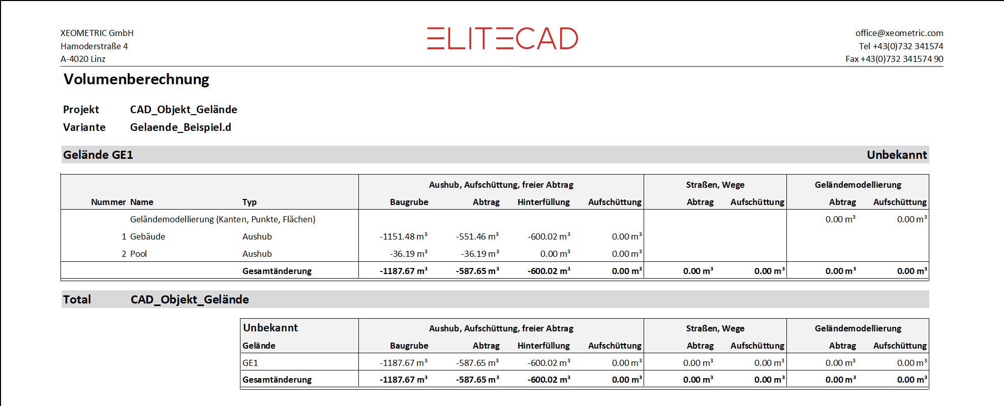
Protocol volume calculation
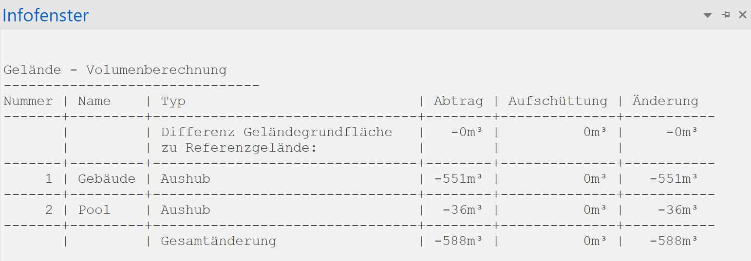
![]()
Only one value is displayed in the property bar for a volume, and that is the total difference. However, each individual modification can mean a removal in one place and a filling in another place. The log gives an exact list of the individual modifications and the overall change in the info window. A name can be specified for the modifications to differentiate between the individual steps.
Terrain quantities
Improved · 17 R1 · Improvements · Highlight video
The volume calculation with all individual modifications can also be output in the form of a quantity report.