Auxiliary lines
The auxiliary lines in ELITECAD are a tool to create a secondary drawing with auxiliary lines with the help of which you can later draw a geometry.
The auxiliary lines remain with the temporary help lines that you have already learned, until you delete them.
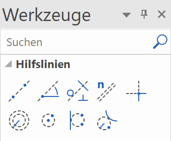
The auxiliary lines consist of lines and circles and are created using the following toolbar:
Lines / circles
Workshop
Create the following auxiliary structure with the auxiliary lines.

- For one horizontal and one vertical auxiliary line as a starting point, use the function STRAIGHT WITH PRESET ANGLE THROUGH POINT.

You can enter multiple angles, separated by a comma.

Click in the centre of the working area.

- The vertical auxiliary lines have 4 times the gap of 200 cm. Select the function PARALLEL STRAIGHTS.

Set distance 200 and 4 copies.

Click NEXT to the line to which the help lines are to be created. Depending on whether the vertical or the horizontal auxiliary line is closer when you click, the lines will be created accordingly.


- The horizontal auxiliary lines have different gaps. They can be created one after the other or all gaps can be created together at once, separated by a comma. Do not forget to reset the number to 1.

Click above the horizontal auxiliary line, which can lie quite a bit outside, so that a vertical help line is not suddenly closer when you click.


- The next auxiliary line has an angle of 35°. Access the function STRAIGHT WITH PRESET ANGLE THROUGH A POINT and set the angle.


- The next help line is perpendicular to the 35° slanting auxiliary line just created. Access the function TANGENT NORMAL ON LINE.

First, determine through which point the auxiliary line is to pass and then to which line it should be perpendicular.
Through which point? Perpendicular to which line?


- The final auxiliary line is an auxiliary circle. The circle must be at a tangent to a straight and pass through two additional points. Start the function CIRCLE BY 3 POINTS OR TANGENTS.

Tangential to the first vertical auxiliary line

1st point 2nd point


- In the auxiliary geometry draw a polygon. The intersection points of the auxiliary construction can now be captured easily.
DRAW function

Start at point P1 and draw until point P7.

The curve is next: Use the Tab key to show the input assistant and select the function CURVE OVER 3 POINTS.
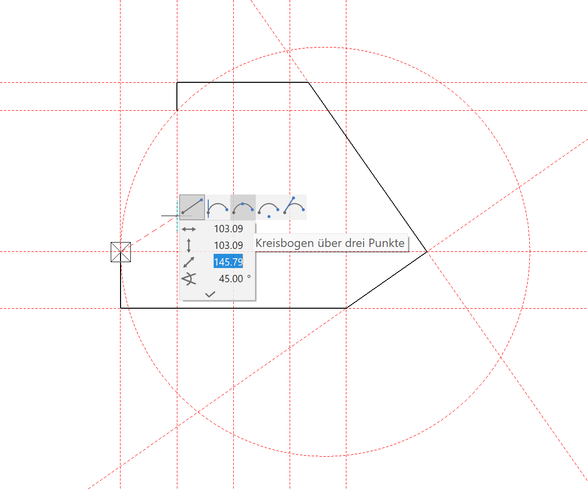
Set P8 on the auxiliary line P9 on the end point


An external wall, a slab or a structure could now be created from this polygon.

- To delete all help lines, select the function DELETE ALL AUXILIARY-GEOMETRY.


- To remove the auxiliary lines from the screen, open a new file.
