Drawing with construction parts
Auxiliary lines
Draw auxiliary lines to define the guide lines of the building.
Workshop
- Create vertical and horizontal auxiliary lines through the origin point of the working plane by clicking on:

- Enter the distance 400 into the property bar with 1 repetition.

- Enter the points P1 and P2 to generate the vertical parallels.
- Enter the distance 250 for the horizontal auxiliary lines into the property bar and set the points P3 and P4.


Work copy
The current stage of work is saved to a temporary directory. A work copy is stored under the name "woco". A certain number of work copies can be made whereby the oldest one in each case is removed and the new one becomes "woco_0".
A work copy is nicht to be used to save the final version of a project!
Save work copy
![]() or with the key combination Ctrl+W
or with the key combination Ctrl+W
Load work copy
![]()
Opens the last work copy (woco_0).
To load an earlier work copies, select the function LOAD WORK COPY in the FILE menu.
Menu FILE > LOAD WORK COPY
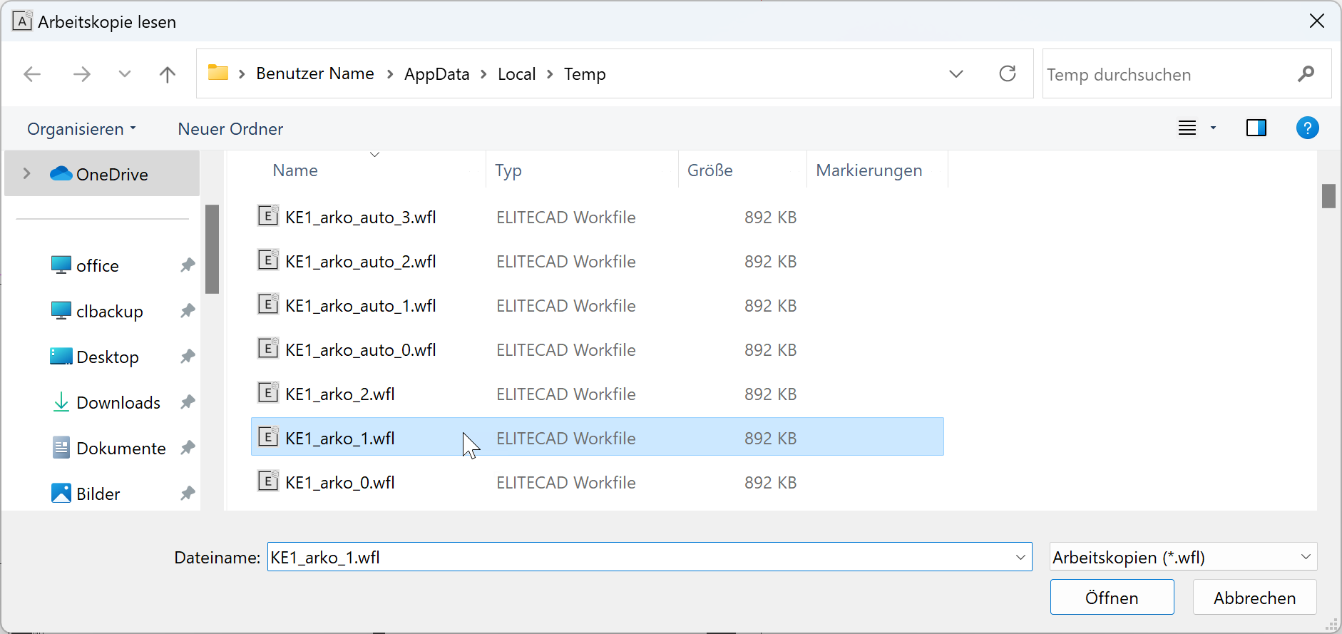
Select the desired woco and click OPEN to import it into the CAD.
All of the settings in connection with work copies can be found in the options.
Menu SETTINGS > OPTIONS > SAVE/LOAD > DRAWING
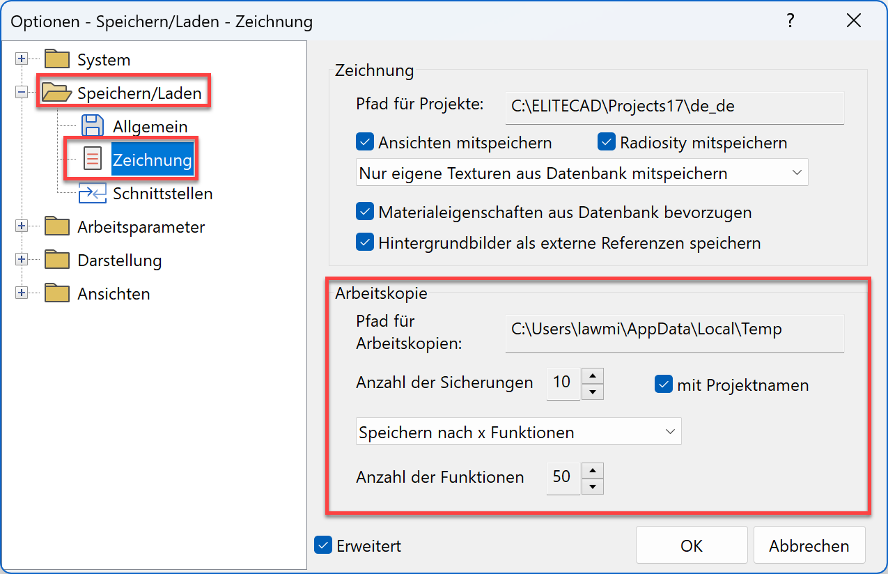
If the "with projectname" option is enabled, the work copies are stored per project.

Slab
On the auxiliary line construction, generate the slab.
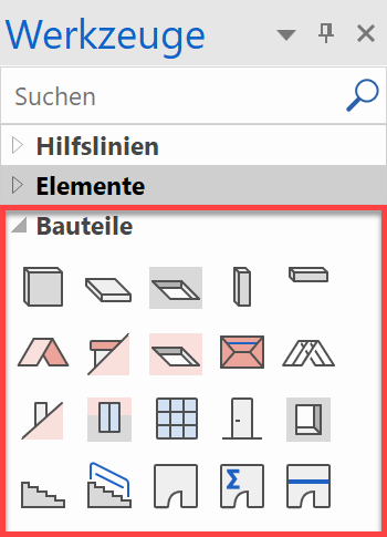
The create functions for the architectural objects (wall, slab, roof, window, door, etc.) are stored in the tools manager under Construction parts.
Workshop
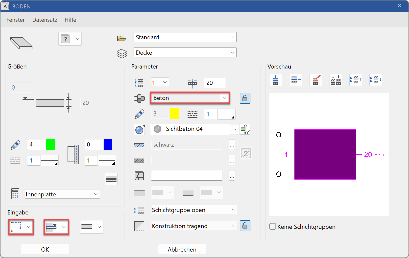
- Select the function CREATE SLAB and open the parameter dialog of the component into the property bar.


- The component can be set in detail in the parameter dialog.
Enter the required settings.
Explanation
Entry mode
A contour was already drawn:
 DEFINE SLAB WITH EXISTING CONTOUR
There is no contour for the slab yet:
 DRAW CONTOUR MANUALLY
 As you have not yet drawn any contour line for the slab, you need to select the option DRAW CONTOUR MANUALLY.
Explanation
Height reference
The height reference determines which height values from the structure settings are used and how the walls respond to the slab. STOREY BASE AS IN VERT. SECTION
Normal storey floor (including basement floor). If a change is made to the height section (e.g. change room height) these floors are corrected. LEVEL FLOOR FOR SHIFTED STOREYS
Is used for all floors that are not storey height or which have a different gauge to the storey floor and should have a reference to the walls. FREE SLAB
The walls have no reference to this slab. Is used in the Surroundings or for special slabs. - In the input assistant (Tab -key) select the drawing function rectangle and drag the rectangle over the points P1 and P2.


- End the function with Esc.
- To check if a slab was actually created, you can switch to the solid view.


The solid view shows you the volume of the slab in the set 3D colour (14) or texture (exposed concrete002).
Return to the wire model.

Use the key combination Ctrl+D to toggle between the wire model to the solid model.
Walls
The next steps teach you how to draw walls.
Workshop
- Select the CREATE WALL function.
The property bar is displayed.

- Select the parameter type "outer wall" and check the remaining values.

Explanation
Height reference
 HEIGHT REFERENCE - FROM LOWER EDGE FLOOR TO CEILING
This option is used for walls that are either not located on a slab or only partially located on one slab, such as the outer wall by which the load-bearing layer is located on the slab and which is passed through by the outer facade layers. - Enter the points P1 - P5. The drawing function Polygon is automatically selected in the input assistant. Of course, you can use the drawing function "Rectangle", exactly as for the slab. As soon as the contour is closed, the system prompts you for the direction.

- Move the cursor into the interior of the structure and left-click. The wall is drawn within the contour.
Tip
The wall axis determines from where the wall is calculated. If you change the wall thickness, the axis remains and the thickness is then taken from this axis again.
In order that the exterior dimensions of a building do not change when the wall thickness is changed, the wall axis must be located on the outer edge. - For the interior walls, select the parameter "Inner wall". Use these values.

- Enter the points P1 - P3. To finish wall entry, click again on the final point (P3). The easiest thing to do is to enter a 0 Enter using the keyboard. Zero stands for the coordinates: x0, y0.

- Determine the direction by moving the cursor into the smaller room P4 and left-clicking.
The wall is created. - Exit the wall function Esc.
- The auxiliary lines are no longer required.
Function DELETE ALL AUXILIARY GEOMETRY.

- Save a work copy.

Doors
This workshop teaches you how to set doors.
Workshop
Entrance doors and internal doors are all 90 cm wide and 200 cm high.

- Select the CREATE DOORS function.
The property bar is displayed.

- Select the parameter type "Standard" and enter these values.

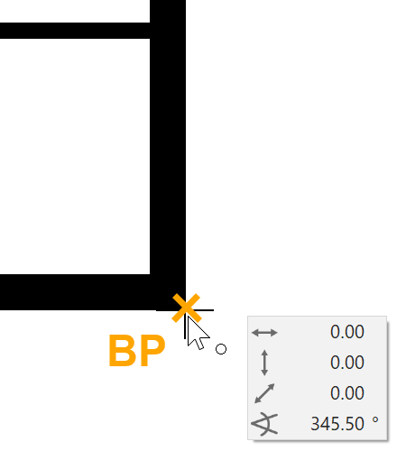
- The doors are at a distance of 60 cm from the corner. Set a temporary reference point RP in the corner.
Move the cursor to the corner and wait briefly. Do not click any of the mouse buttons. The symbol of the reference point, an orange cross, appears.
- Now move the cursor to the outer wall into which the doors are to be placed. The capture symbol "To element" must be displayed. Now press the Tab key.
Now enter 60 cm into the direct value field and confirm.


- Now move the cursor. Depending on the location, the doors open outwards or inwards and are shown either left- or right-hinged. If the preview corresponds to the position and opening direction, confirm with Enter.


Tip
The door leaf is shown open at 70° and is only visible in 3D. In the 2D floor plan it is switched off. In the detail settings for the door leaf, this value can also be changed.
3D Display 2D Display 

- Now set the second door. Set a temporary reference point in the reveal of the doors just set. You can now capture the section point of the inner wall with the temporary reference point.

- Position the doors with the correct opening type.

- Cancel the function Esc and save a workcopy with Ctrl+W.
Windows
Process for setting a window:
- Set reference point
- Specify the direction using the cursor, enter the distance
- Specify the type of placement P1
Important: During placement, the outer side of the window is marked with a line. Move the cursor outside the building to set the window.

Workshop
Develop the floor plan further with windows.

- Select the function CREATE WINDOW.
The property bar is displayed.

- Select the type "Standard stop" and set the values as shown.

- Set a temporary reference point in the upper right, outer corner, move the cursor onto the outer wall and enter the gap 100 into the value field. Next, position the window.


- For the second window, set the reference point onto the reveal of the first window. Zoom in sufficiently so that you can be sure that you have not hit the corner of the window sill. The distance between the two windows is 60 cm.

Position the windows

- Enter the values for the two large windows into the property bar.

The two windows are both in the middle of the wall section. Move the cursor along the wall until the capture symbol Middle of element appears and centre the window.


- Cancel the function Esc and save a workcopy with Ctrl+W.
Change of storey
You have now successfully drawn the ground floor.
The same elements on the ground floor can be transferred to the top floor. Use the function COPY INTO ACTIVE STOREY to copy the selected objects of other storeys to the current storey.
![]()
Workshop
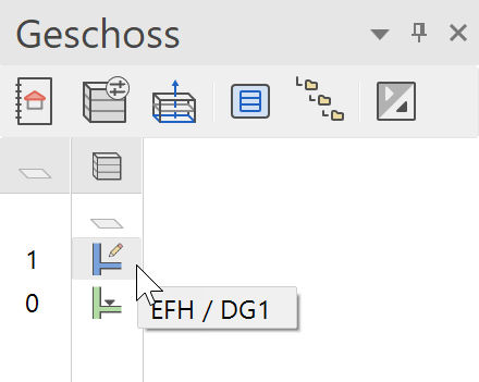
- Select the top floor as current storey in the Storeys manager.
Click on TF1 > TF1 turns blue.
- Using the centre mouse button, rotate the model somewhat to the side so that you can see it in 3D.
- Switch from the wire model to the solid design model.


- Select the function COPY INTO ACTIVE STOREY.

- Select the floor with your mouse. The result is displayed immediately.

- Back to the starting point and into the wire model
 +
+  or Ctrl+D + Ctrl+Space
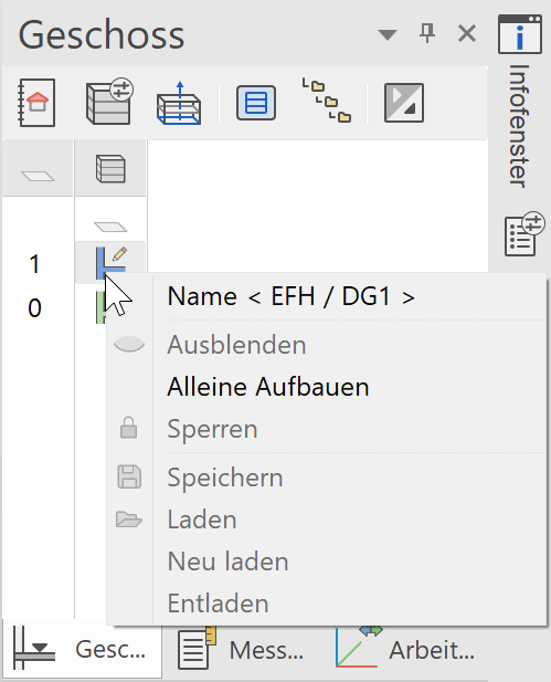
Storeys manager
Right-click on a storey to display the context menu.
In this menu, you can manage the visibility of the individual storeys. You then only have the data on the screen that you actually need.
Top floor
Workshop
Create the jamb wall in the top floor.
- Function CREATE WALL
- Enter the values into the property bar.

Tip
Use the HEIGHT REFERENCE - FROM LOWER EDGE FLOOR TO CEILING for the uppermost wall as well. The roof takes on the role of ceiling and the wall is automatically limited by the roof.
- To enable the wall to be set more easily, you can temporarily switch off the hatch.

- Draw the wall by clicking on the points of the outer edge of the building. The wall faces inwards.

- Show the hatch again.

- Cancel the function with Esc.
Roof
Workshop
The house shall have a gabled roof. To construct a gabled roof you require an outline, the location of the ridge and a height marker.
- When you double-click on the top floor, it is created by itself.
- Select the function PARALLEL STRAIGHTS, enter the distance in the property bar and position the auxiliary lines.

P1, P2 - For the vertical auxiliary lines, set the gap in the property bar and position the auxiliary lines.

P3, P4

- If you select the function CREATE ROOF, the property bar will appear.
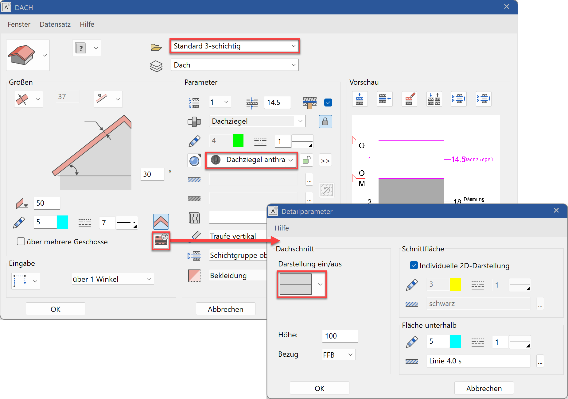
- Open the roof parameters from the property bar.

- Select the type "Standard 3-layers" and make the settings. Switch off the display of the roof section in the detail parameters.
- From the input assistant, select the drawing function rectangle and drag the rectangle up over the points P1 and P2.

- The position of the ridge side must now be defined. Move the cursor into the centre of the element until the capture symbol Middle of element appears P3. The second ridge side is located precisely horizontally so that you can move the mouse to the right until the temporary help line appears with 0° > P4.

- You can position the height marker anywhere in the floor plan. In our example, the height is measured on the inside edge of the wall > P5.


- The auxiliary lines are no longer required. Remove the auxiliary lines using the function DELETE ALL AUXILIARY-GEOMETRY.
- Select the function SHOW. If no element is selected the entire model will be displayed.

- Cancel the function with Esc.