Light shafts
Light shaft (Library part)
There are a number of options for creating the light shafts.
- only as a 2D floor plan in the plan
- set a library part
- as a 3D object created from a library part or a polygon you drew yourself
Workshop
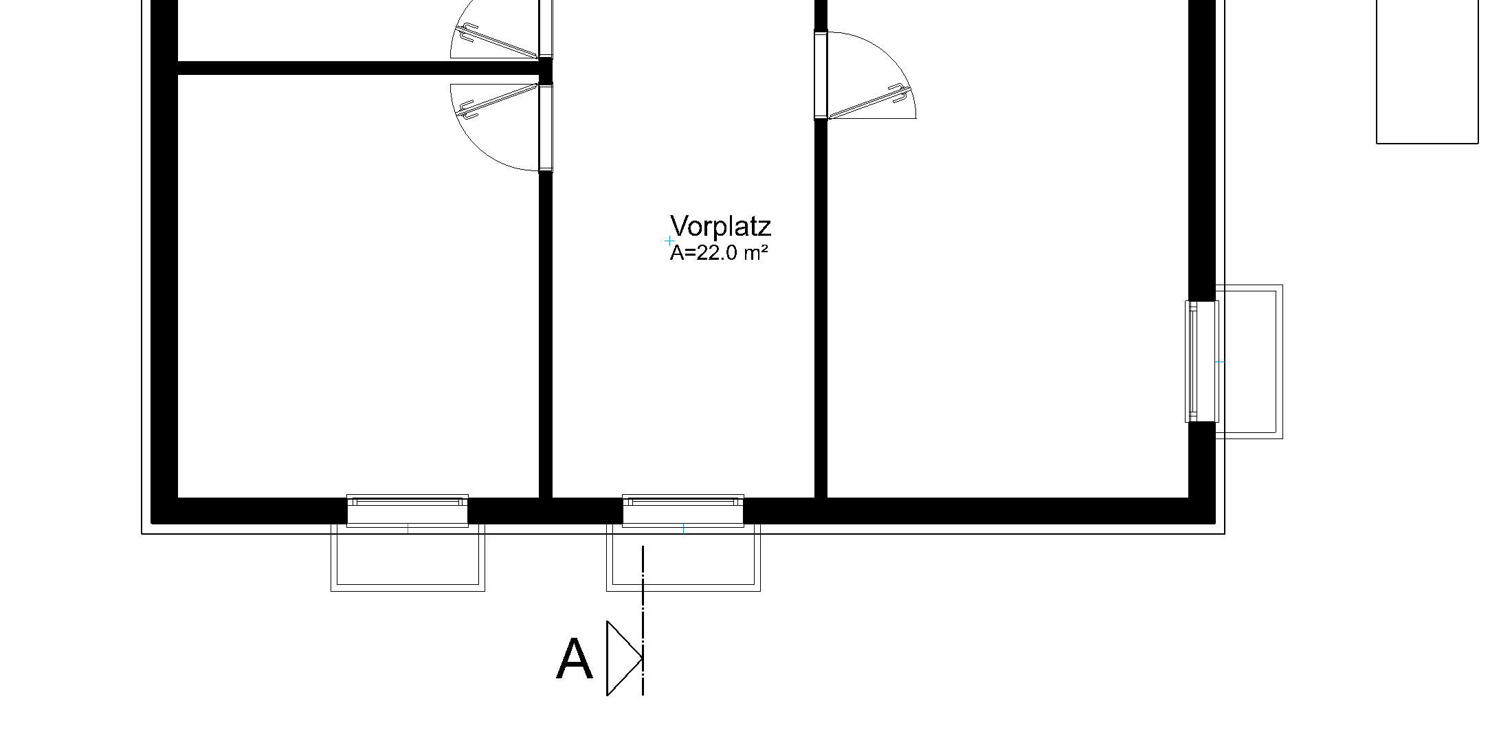
You must create 3 light shafts. The size of the light shafts is 60x140 cm and can be taken from the library.
- Activate the basement and select show alone from the context menu.
- Bring library manager to the foreground (Ctrl+3)
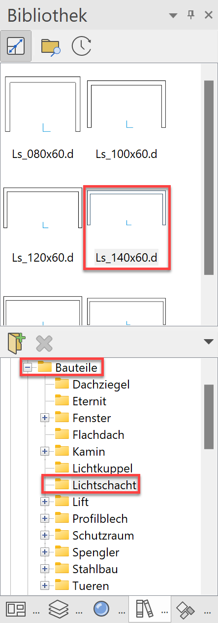
Switch to the path components/light shaft. Select the light shaft "ls_140x60.d".
- You now have the light shaft attached to your cursor.

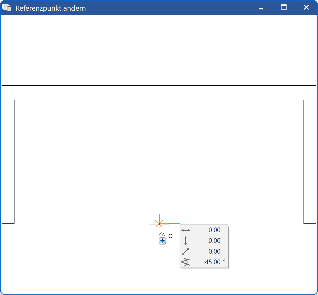
As soon as the library part is attached to the cursor, the property bar appears. To enable the light shaft to be better placed, you must move the reference point.
- Select the function MODIFY REFERENCE POINT from the property bar. A new window opens with the light shaft. Now select the new reference point in the centre of the light shaft.

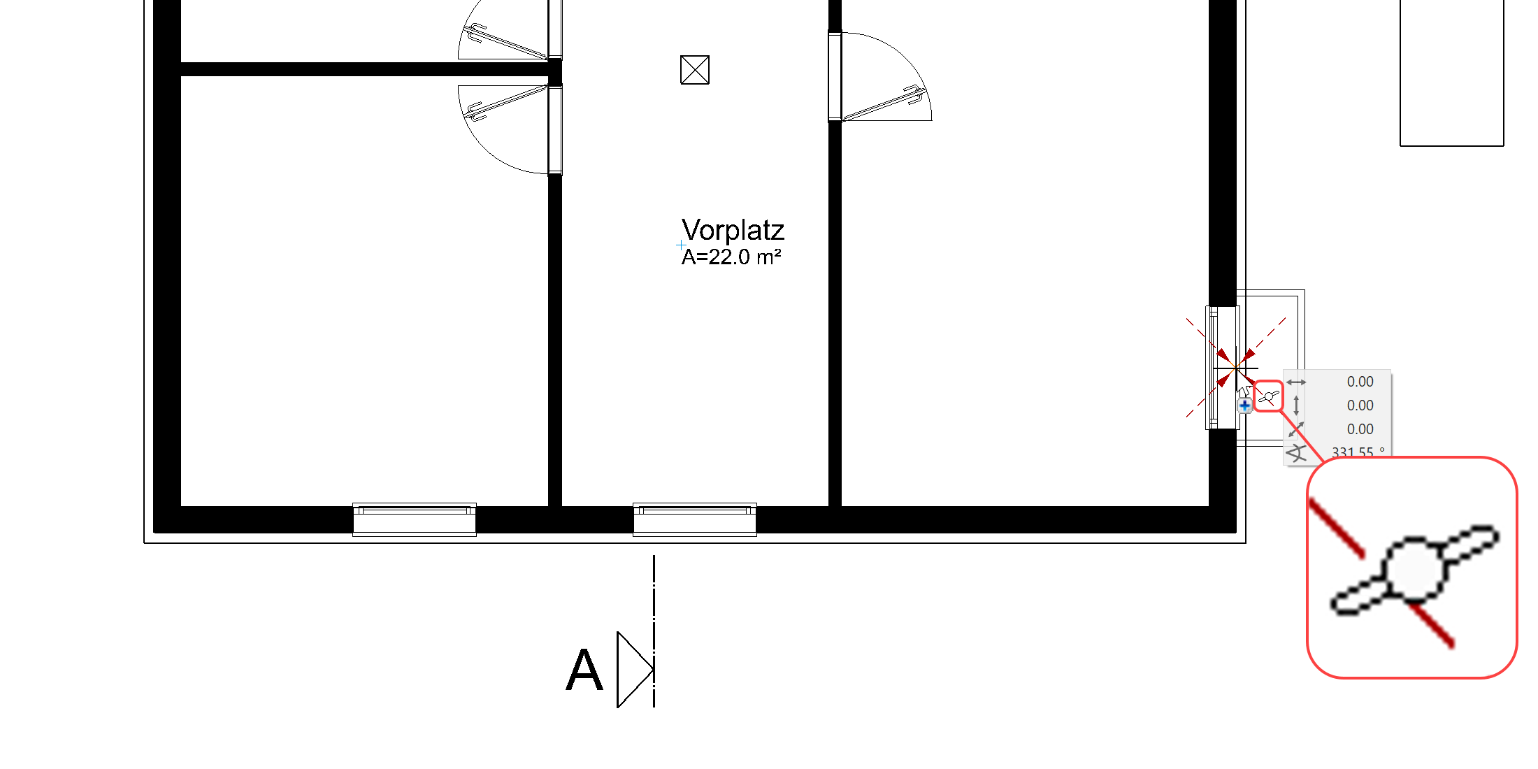
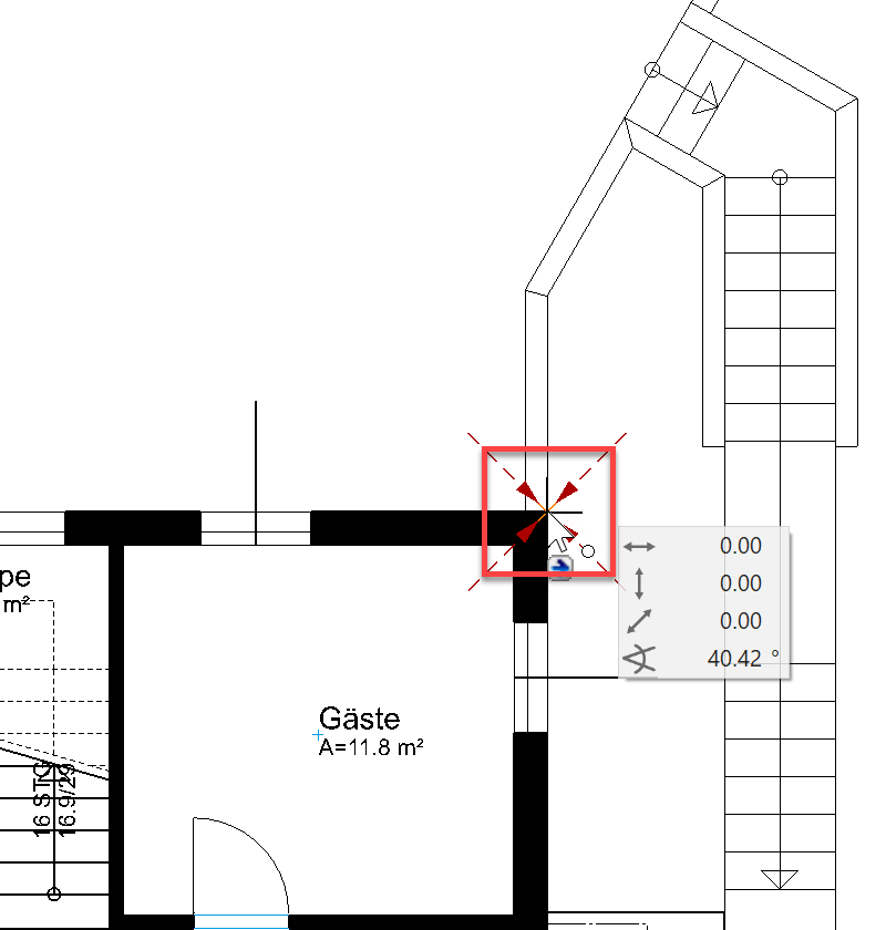
After clicking on the new reference point, the dialog disappears again and you now have the light shaft in the centre of the cursor. - Turn the light shaft by 90° using the function ROTATE CLOCKWISE in the property bar.

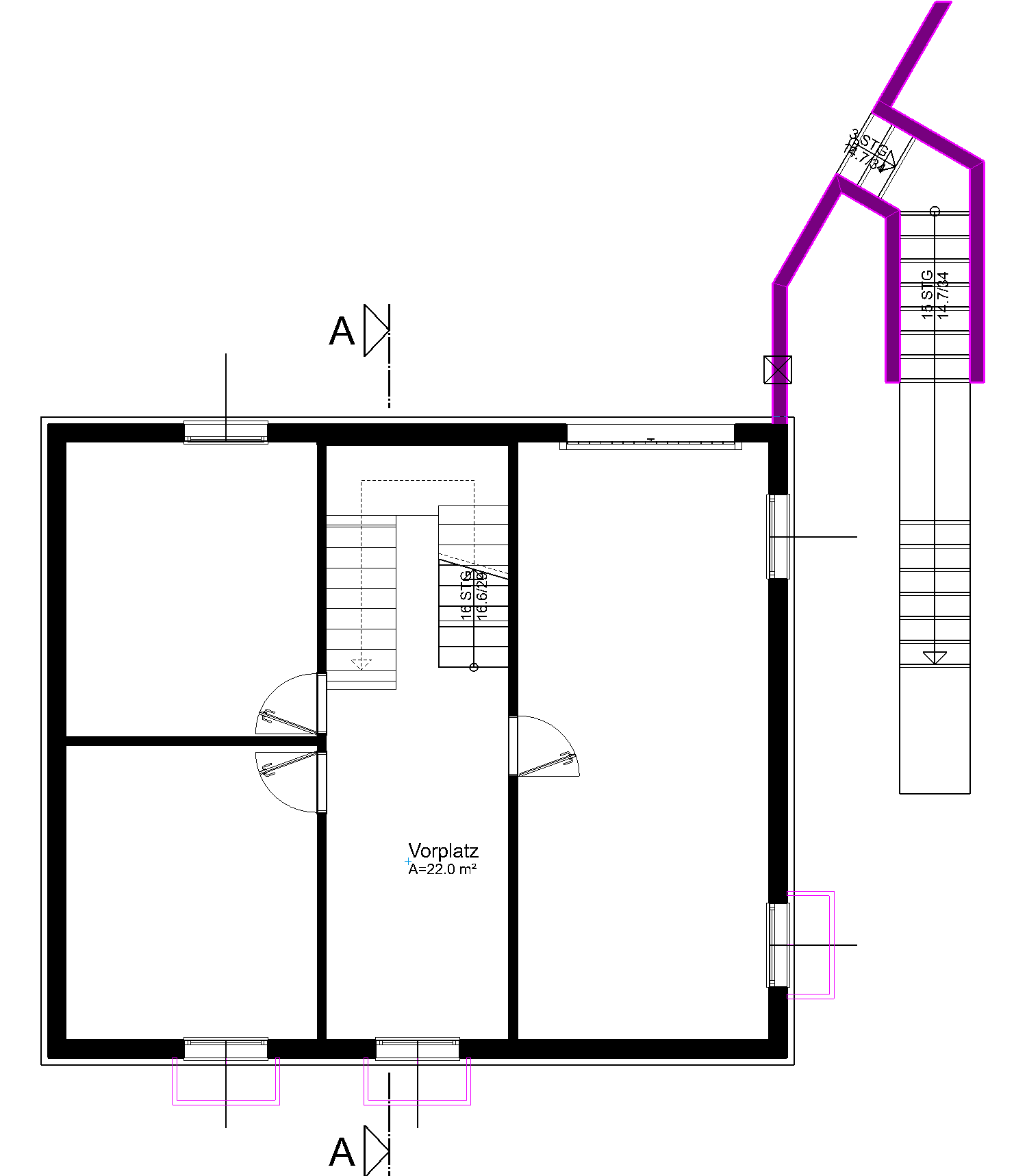
The light shaft is now perpendicular on the cursor. - Locate the light shaft in the middle of the basement window.
- Rotate the light shaft by 90° again locate the two lower light shafts as well.

- Cancel the function with Esc.
3D Object for light shaft
Workshop
The light shafts are 2D library parts. A 3D object must be assigned to these floor plans.
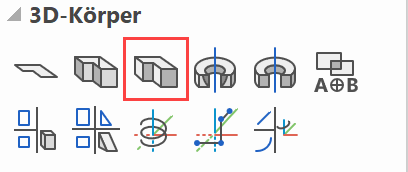
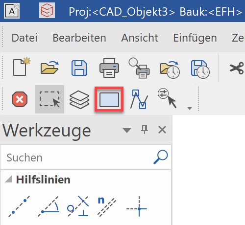
- Select the function DEFINE BOX.
- Determine the lower and upper height of the box (measured from the current work plane currently -2.70), and the entry mode Select contour.

- Click on every light shaft floor plan and end with Esc. The 3D object is immediately created.

Tip

Click on colour preview to open the colour tables.
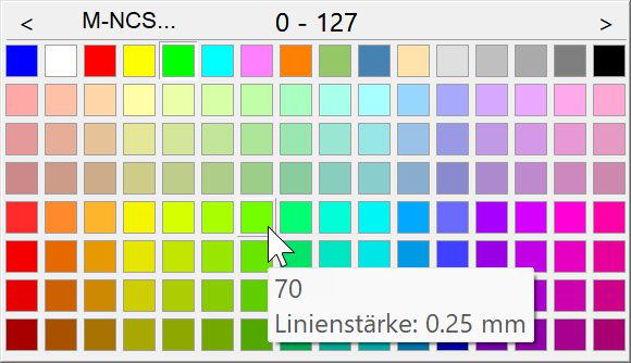
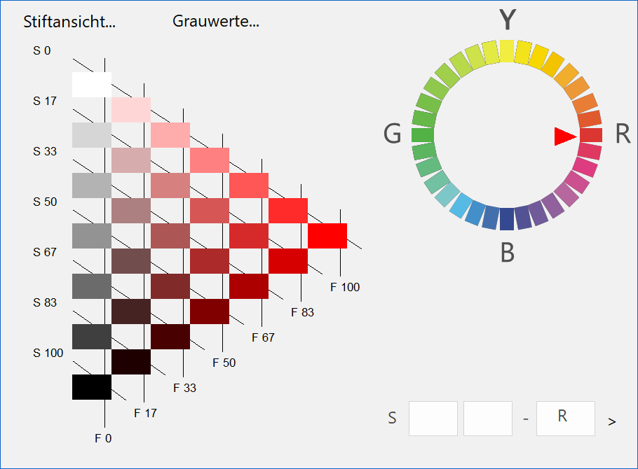
Use the arrows < > to navigate a table backwards and forwards. When you click on the button, you see a different view of the colour tables.
 - The 3D object initially has the standard settings. Select a light shaft for editing.

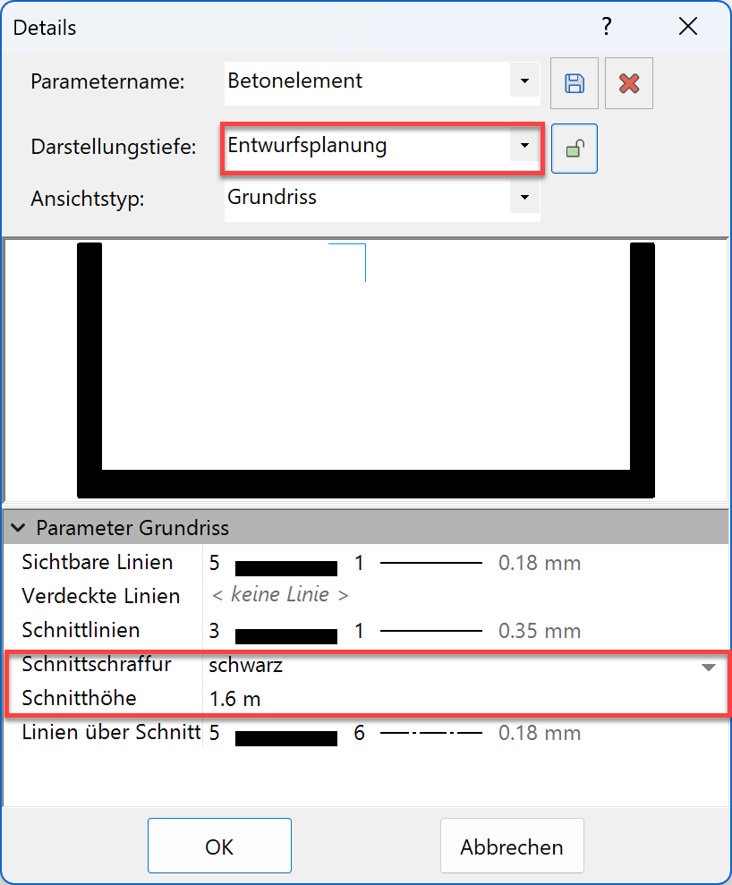
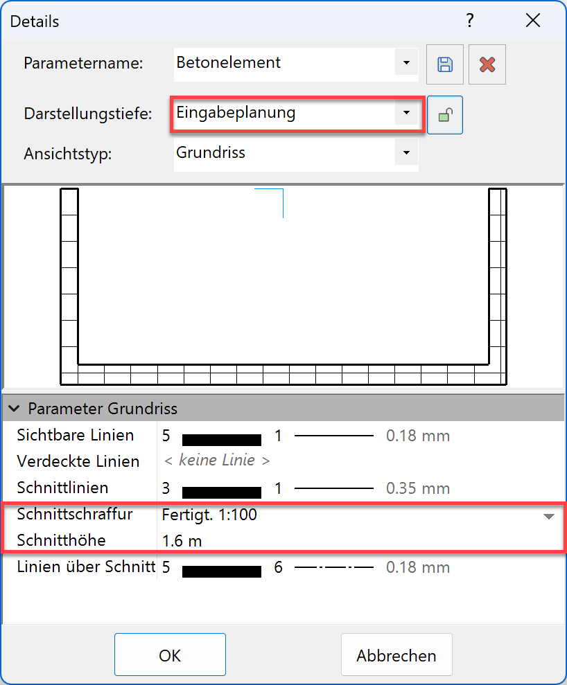
- In the property bar, open the parameter dialog and select the detail parameters.


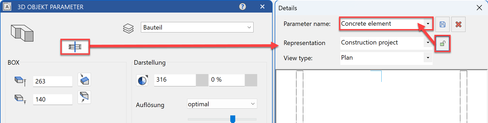
Remove the link to the representation level and select the parameter record Concrete element. - Change the section height to 1.60 m and select the desired hatches for each representation level.
- The change to one light shaft must be transferred to the other two light shafts. Select the function COPY PARAMETERS and the light shaft you have just modified.

- On the "Copy parameters" dialog, you can determine precisely which parameter values are to be transferred to the other objects. In this case, selecting the indicator for the representation level would be enough but it is also okay for all entries to be active since all light shafts have the same colour and height.
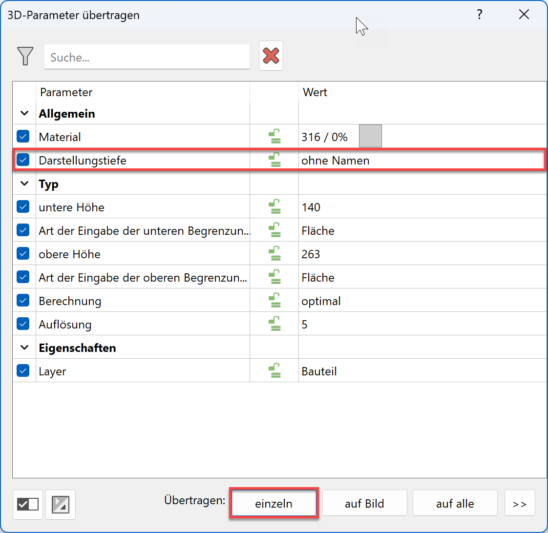
- Select the transfer type single and click on the other two light shafts (click in the 3D model on the box).
- Cancel the function with Esc.
Top views of components
The components are only represented on the floor plan in the storey they were created. This is with the exception of stairs and windows that extend across separate storeys.
Workshop
The retaining walls and the light shafts must also be represented on the ground floor.
- Activate the basement and select show alone from the context menu.
- Select all objects that are to receive a top view. Hold down the Shift key and select the 3 light shafts and the 3 retaining walls.

- Select the SHOW function.

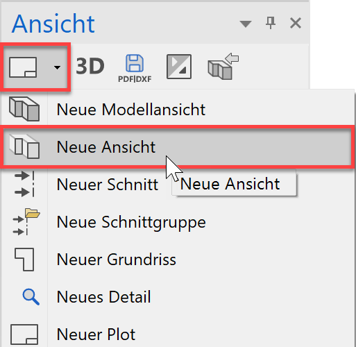
Only the selected parts are visible on the screen. - Create a view from the visible selection. Select the function NEW VIEW in the Views manager.
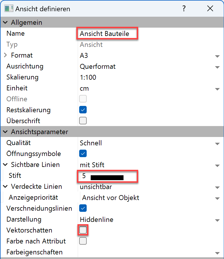
- Enter the name Components View and make the settings.
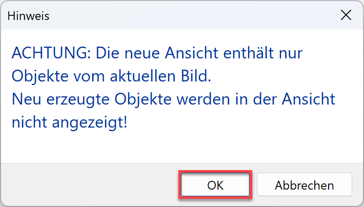
- A message appears that newly generated objects in this view are not displayed.
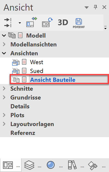
- You can access the view in Views manager.
- The top views of components must be copied from the view to the ground floor. Use the SELECTION IMAGE function or the key combination Ctrl+A, to select all objects in the view.
- Copy the selected objects to the clipboard.
(or key combination Ctrl+C)

- To enable the objects to be set precisely, a reference point must be specified. Select the corner of the retaining wall that corresponds to the corner of the building and which can therefore be easily placed in the ground floor.

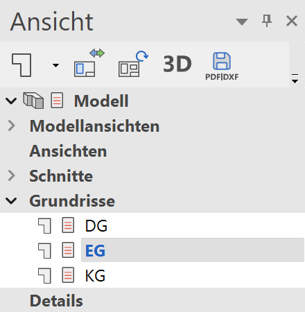
- Switch to the plan view GF.
- Paste the copied selection from the clipboard into the plan.
(or key combination Ctrl+V)

- The objects are "attached" to the selected reference point on the cursor. Position the selection in the plan.
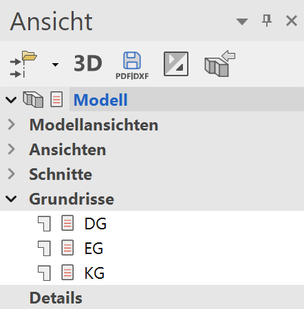
- Switch back to the model and reconstruct the whole drawing.
 +
+