Porch
Gradient slab
The forecourt must be inclined. In the parameter dialog of the slab, you can switch between a level and a sloping slab. The gradient slab is determined by an incline percentage, the highest point of the upper edge of the slab and the direction of the incline.
The level of the floor is measured from the current work plane. The work planes of the floors are located on the raw markers of the ceilings.
Workshop

- Activate the ground floor and make the basement visible.
- The height for the floor (measured as from the current work plane) can be calculated as follows:
Marker basement: -270; marker GF: -10
Stair heights: 44.1cm + 220.5cm = 264.6cm
Floor height = 4.6; marker +-0.00 = -5.4It is much easier to access the height directly from the model:
Open the dimension functions from the context menu (right-click in the background).
Start the function COORDINATES OF POINT.


Click on the upper edge P1 (see image above) of the last step.
The info window is to the top right of the edge of the screen. The info window opens as soon as you move your cursor into the field.
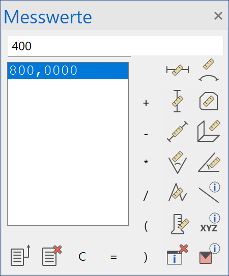

Two rows are displayed in the info window:
REL = height to current work plane: X value, Y value, Z value
ABS = height marker to +/- 0.00 of the structure: X value, Y value, Z value
- The basement is no longer required; switch the basement to invisible.
- Select the function CREATE SLAB and open the parameter dialog.


Set the parameter (1)record. The material (2) is concrete; the free slab type (3) and slanted (4). The upper side of the slab is set to 4.6 (5) and has a thickness (6) of 14.7 cm. The height is measured at the lowest point(7). There should be a gradient of 2% (8) from this point. The thickness (6) is measured at the thinnest point (9). The lower edge of the slab must remain horizontal (10). The slab must be quantified as an "exterior slab" (11).
- In the input assistant, switch to the drawing function RECTANGLE.

- Draw the rectangle for the porch. Start at P1. The second point is located 30 cm above the door opening. Make use of a temporary reference point.


- The two following prompts relate to the upper edge P3 (point at which the height entered (in field 5 from step 4 above) should count) and the direction of slope P4.

- Cancel the function with Esc.
- Korrigieren Sie die Textur, falls die Treppen und Podestböden noch nicht mit der Textur „Sichtbeton002“ belegt sind. Siehe Kapitel Texturen zuweisen.

Porch roof
There will be a small glass porch roof over the entrance.
Workshop
- Create parallel auxiliary lines to draw the roof contour.

- Select the function CREATE ROOF and open the parameter dialog.


Change the roof type (1) to flat roof. Select a layer (2) and delete (3) it until only one layer is left. The thickness (4) of this layer is 2 cm and it is made of the material (5) glass. Determine the texture (6) and the transparency (7). Activate the option (8) so that the texture is displayed on all sides. The height (9) of the roof is 230 cm.

- In the input assistant, switch to the drawing function RECTANGLE.
- Extend the rectangle above the porch from point P1 to point P2.

- Cancel the function with Esc.

Outer door
You may have noticed that the threshold of the front door has a dip. We will now correct that.
Workshop
- Start by selecting the door itself. From here we can easily change this.

- In the property bar, change the threshold from 0 to 10.

- The door should now look like this.
