Retaining wall
Workshop
Retaining walls must be created along the garage entrance and staircase. The retaining walls extend 1 metre below basement level.
For the external staircase, you have created a secondary drawing with auxiliary lines. If you deleted the auxiliary lines, add the missing auxiliary lines in the same way as step 2 of the External staircase.
- Activate the basement and select show alone from the context menu.
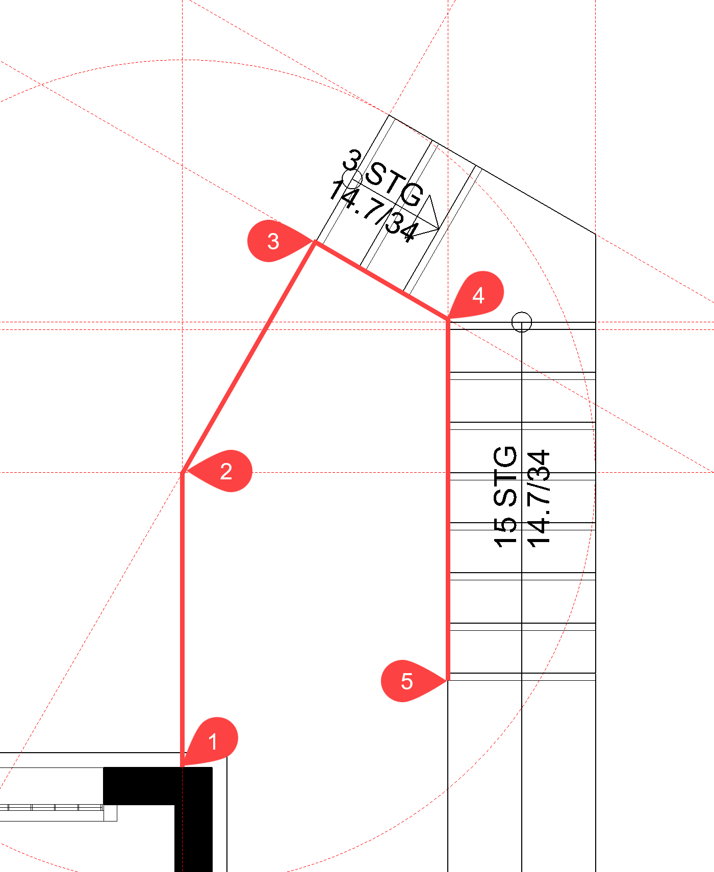
- Select the function CREATE WALL. In the property bar switch the parameter record to Concrete and change the rest of the values. The wall height is changed following modification. The bottom edge of the wall is set to –100.


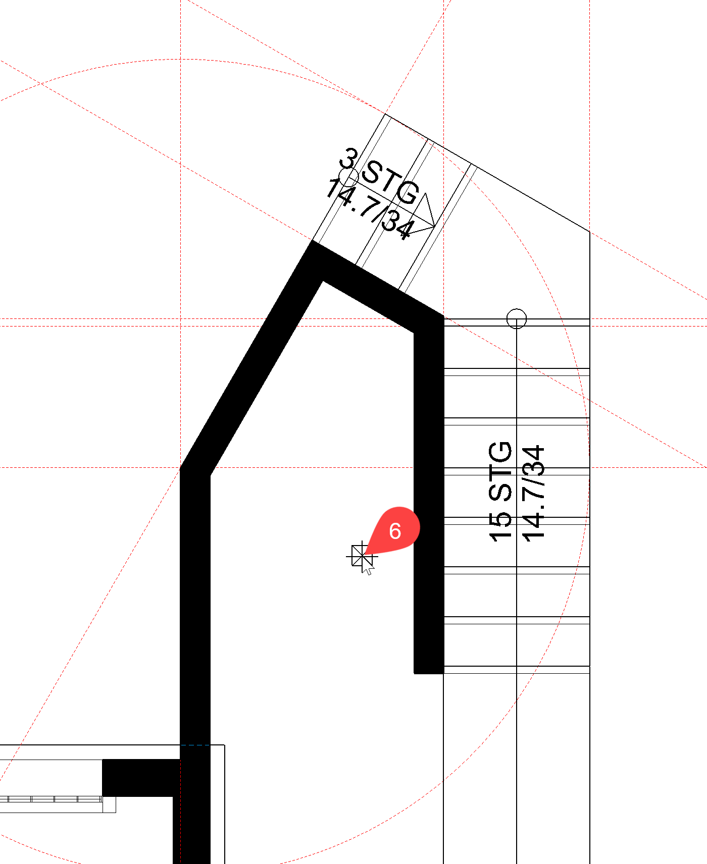
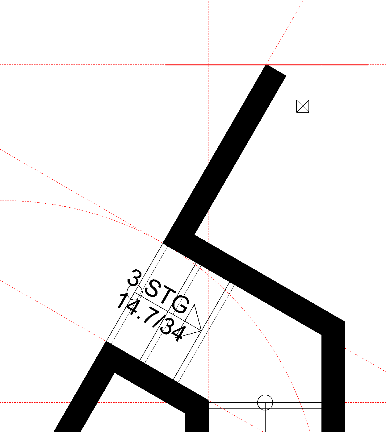
- Start at point P1 and move along the auxiliary lines and staircase to point P5. For point P4, zoom in sufficiently so that you capture the corner of the landing and not the edge of the stair. Click again to confirm the end of the polygon P5 and determine the direction of the wall P6.
- Cancel the function with Esc.
- Rotate the model in 3D and switch to solid mode.
- Select the retaining wall just created. A wall with a wall height reference does not just have handles in the floor plan but also in the Z-direction. Move your cursor onto the upper height handle (triangle). The cursor switches to a double arrow. Click on the handle. The upper edge of the wall is now "attached" to the cursor. The wall must have the same height as the intermediate landing of the staircase. Point the cursor to the upper edge of the landing and confirm it as soon as point capture is displayed.


- In the property bar, the new height is displayed as 261.7. The retaining wall should extend slightly beyond the landing. Change the height to 264.


- Cancel the function with Esc.
Switch back to the wire model and to the starting position. - Restart the wall function. As the settings are the same as those when exiting, you can draw the second retaining wall immediately.
- Cancel the function with Esc.
The 3D model should now look as follows in the solid model:

Wall with inclined upper edge
Definition of an inclined wall upper edge or wall lower edge
The angle of the edge can be entered in two different ways:
by 3 points:
Specify 3 points to determine the height.
by planes:
If a surface already exists with the same slope, the surface can be selected directly in the model (solid model mode).
Example:
To define the upper edge of the wall, the bottom view of the staircase was selected.

The wall can only have one slope. If there are multiple kinks, the wall must be interrupted.
Workshop
- Select the function CREATE WALL. In the property bar, change the wall upper edge to Shape – slanted above.

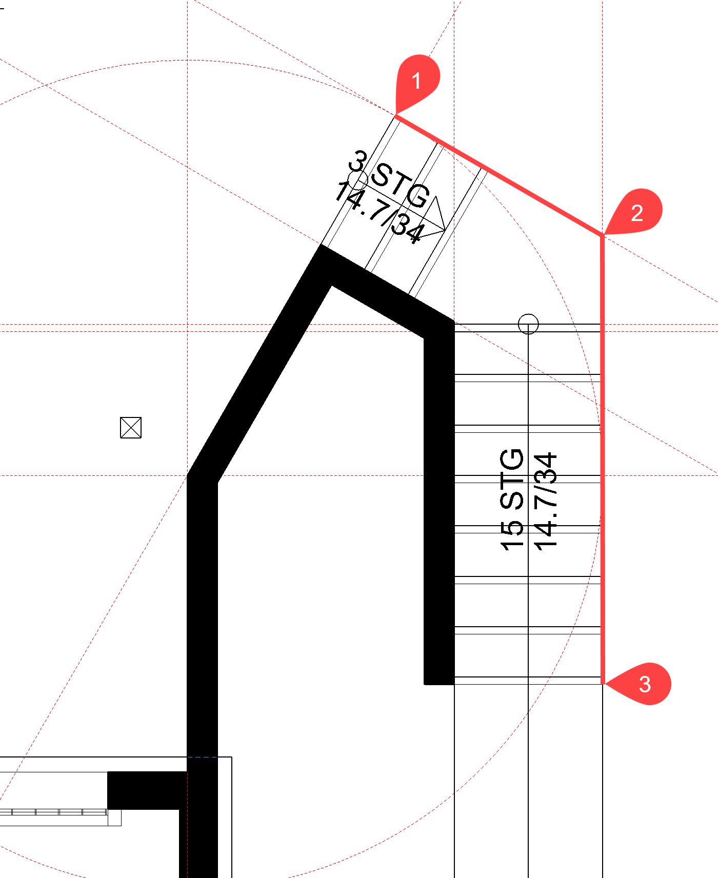
- Start at point P1 and end the wall by double-clicking at point P2. Specify the direction of the wall > P3.
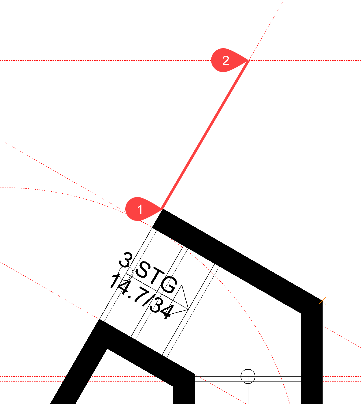
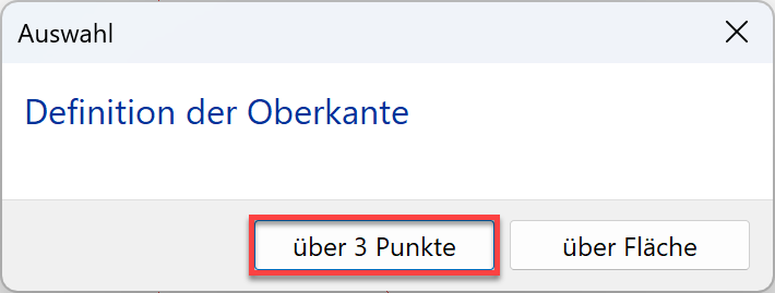
- A prompt now appears asking how the upper edge is to be defined. In this case, the upper edge is defined by 3 points.
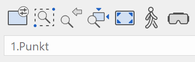
- The first of the 3 points is point P4. The height of the retaining wall at this point is 20 cm. Enter the value 20 into the input line and confirm the value.


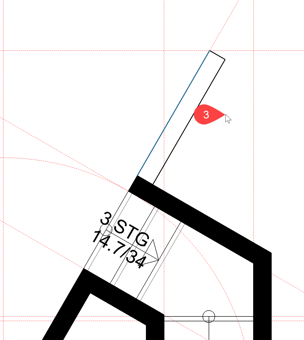
- The second and third height marker can be selected directly in the 3D model.
Rotate in 3D and into the solid display.
The second point of the retaining wall is point P5, height 164 is entered directly in the input line and must be confirmed.
The third point of the retaining wall is point P6 with height 164.

- Cancel the function with Esc.
Modify wall ending
A wall ending is perpendicular. The function DEFINE WALL ENDING can be used to define a sloping or a special ending. The ending is drawn as a polygon from one side of the wall to the other. The layers of a wall are not important.

Workshop
The upper wall ending of the inclined wall just created is to be horizontal and not perpendicular to the wall axis.
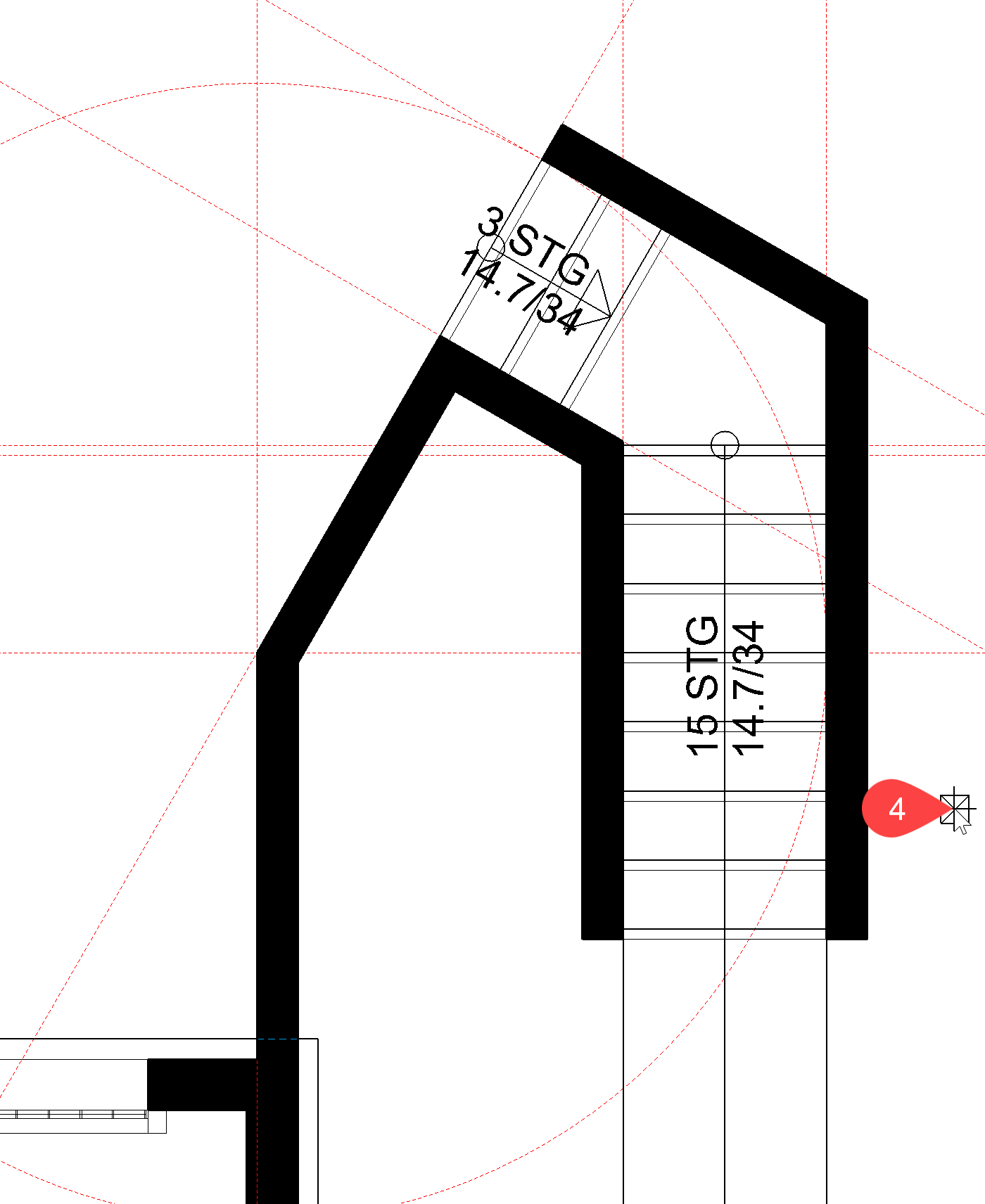
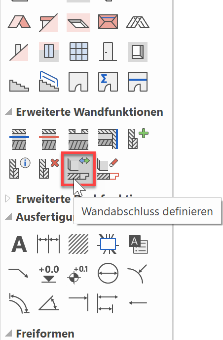
- Start the function CHANGE WALL ENDING and select the wall to be changed > P1.


- Draw the new wall end. The line does not have to start on the outer side of the wall but can overlap if necessary. Start point P2 and the end point P3 (Double-click)
- Remove the auxiliary lines.
