External dimensions
The floor plan can now be measured using the different options for architectural measurement. It does not matter whether you measure in the model or in the plan view. The correct floor must be active in the model. Like construction parts, measurements can be copied to the current floor.
Workshop
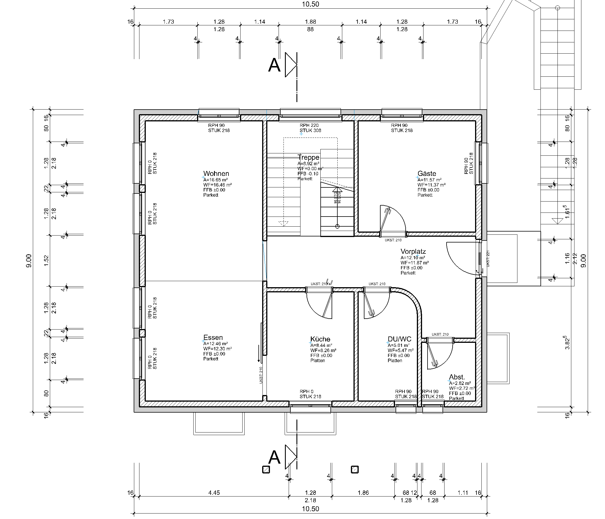
- Prepare the position of the external dimensioning using auxiliary lines.

Create auxiliary lines with a distance of 300 cm from the walls.
- Click on the function CHAIN DIMENSION.

Switch to the Parameter group 1.

- Create the vertical main dimension. Set the two dimension points P1 and P2, set the position of the dimension chain P3.
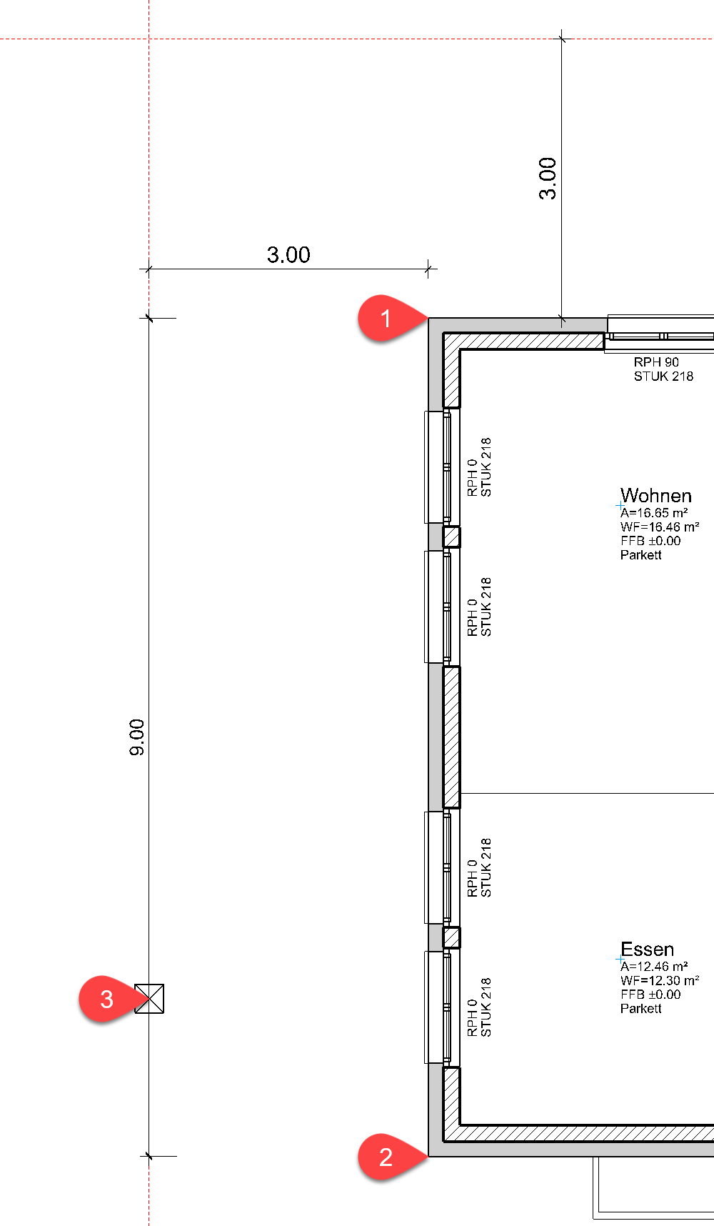
- To start a new dimension chain, you either need to restart the function CHAIN DIMENSION or you select the function AUTOMATIC on the property bar.

- Create the horizontal main dimension. Set the two dimension points P4 snd P5, set the position of the dimension chain P6.
- Start a new dimension chain.

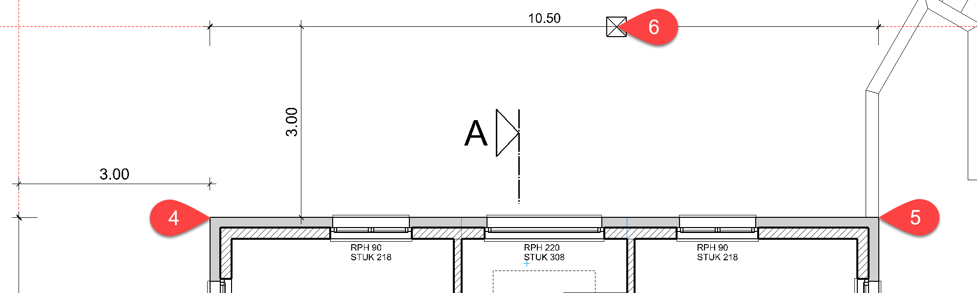
- Switch to the PARAMETER GROUP 2. In the additional functions, open the PARAMETER FOR OPENING DIMENSIONING. In the settings, you can determine the desired options for the points to be measured.


- Under additional functions, select the OPENING DIMENSION.

- The opening dimensioning consists of a reference line, defined by the start and end point, and the position of the dimension chain. The program automatically searches all openings on this reference line and measures them. The reference line must be located on the outside or inside of the wall, but not necessarily on the end points. The result will vary depending on the position and window type (stop).
Specify the points P7 and P8 for the reference line and click for the position on the text of the primary dimension P9.
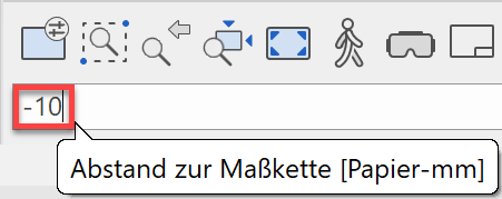
In the input line, specify the distance to the primary dimension. Downwards and left the gap is a negative value.
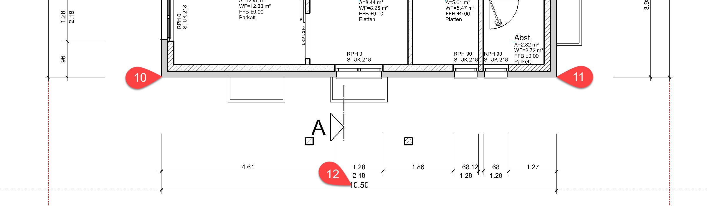
- Start a new dimension chain and select the opening dimension again. The additional functions must be reselected for every dimension chain.
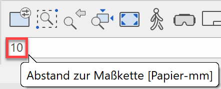
- Specify the points P10 and P11 for the reference line. For the position, click on the text of the primary dimension P12 and enter the distance 10.
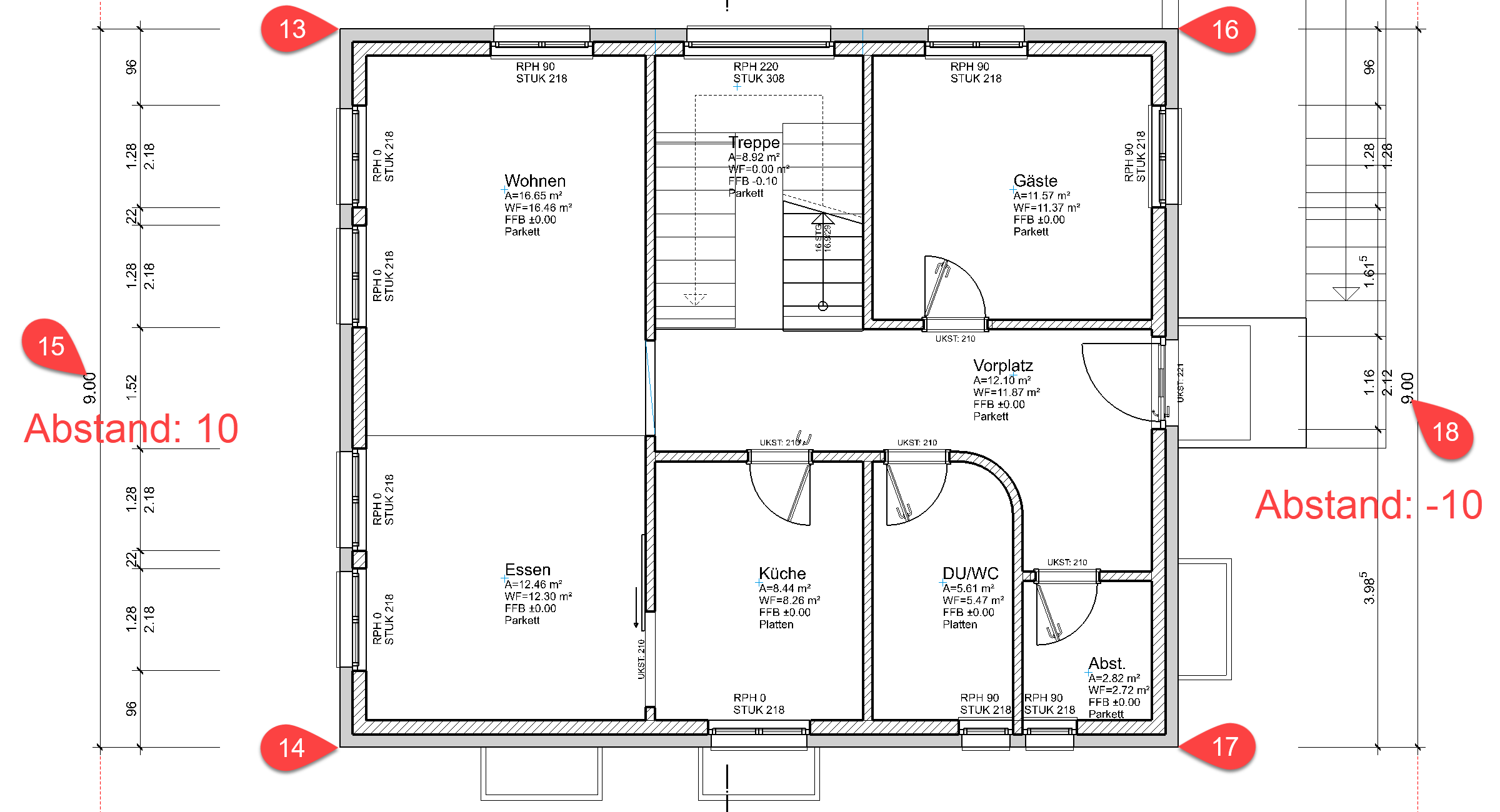
- Generate the secondary dimension for the two vertical primary dimensions. P13-P18
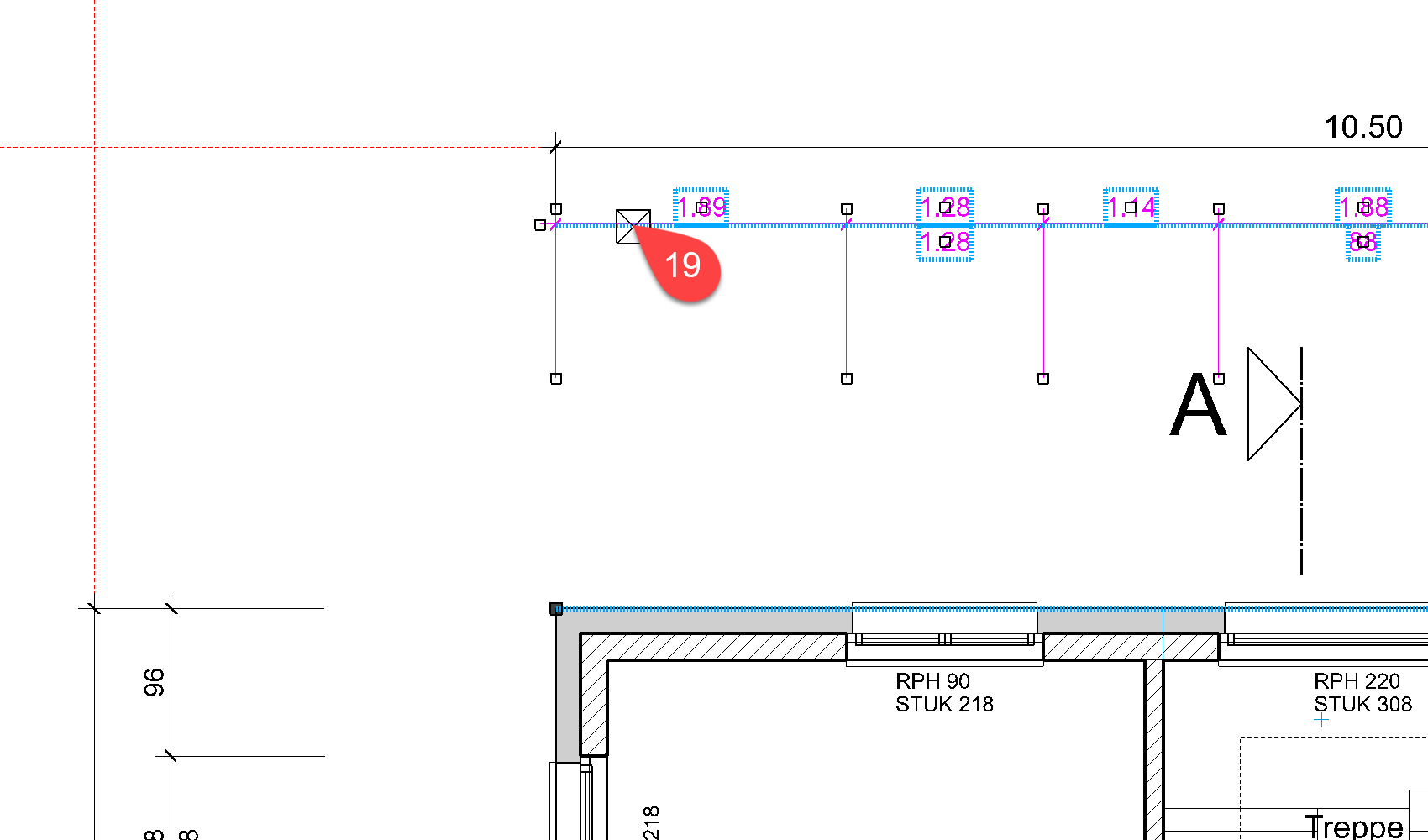
- Add the dimension points for the brick wall. Edit the dimension. P19
- Select the function “DEFINE MEASURING POINT”. Add the dimension point P20.

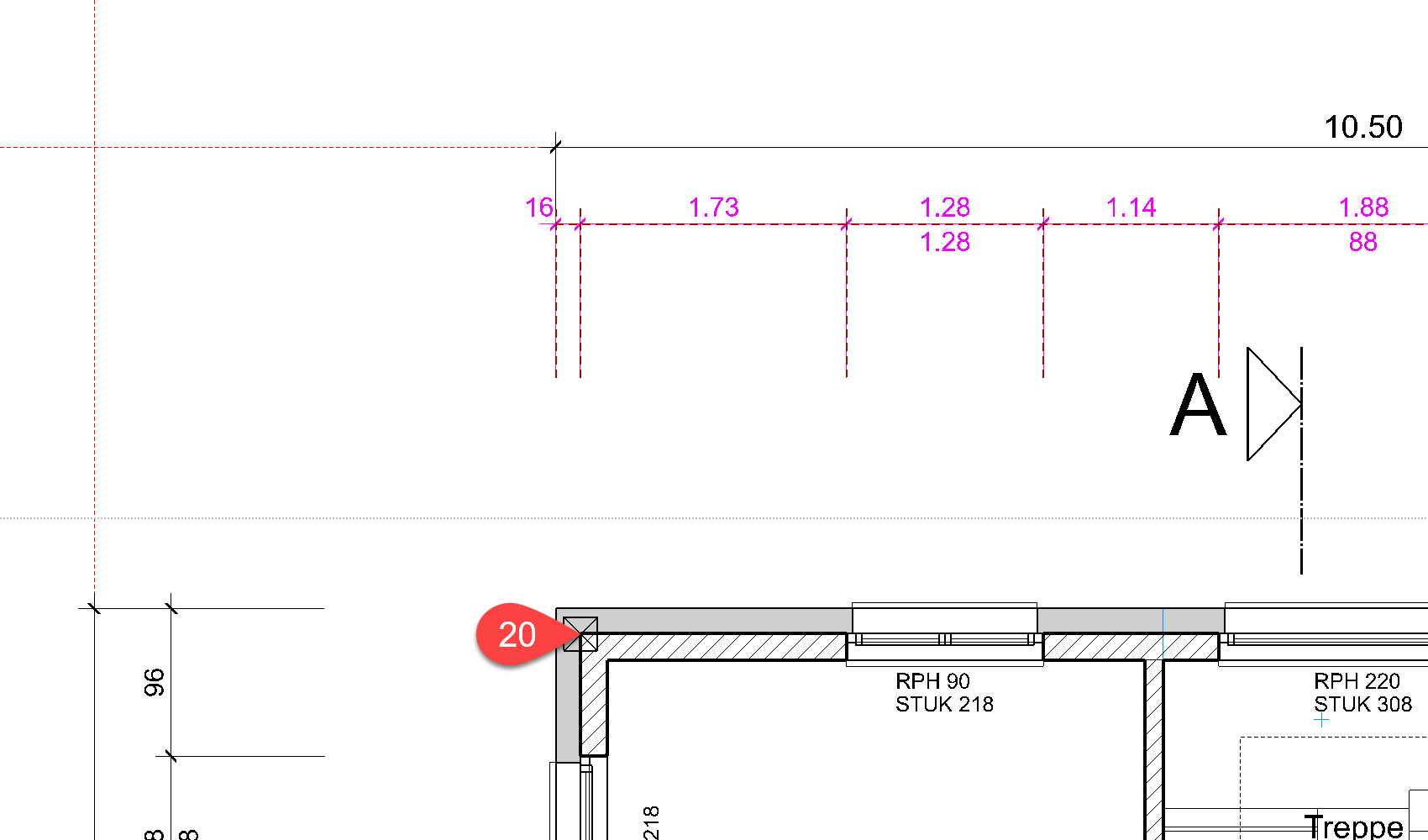
- Cancel the function Esc.
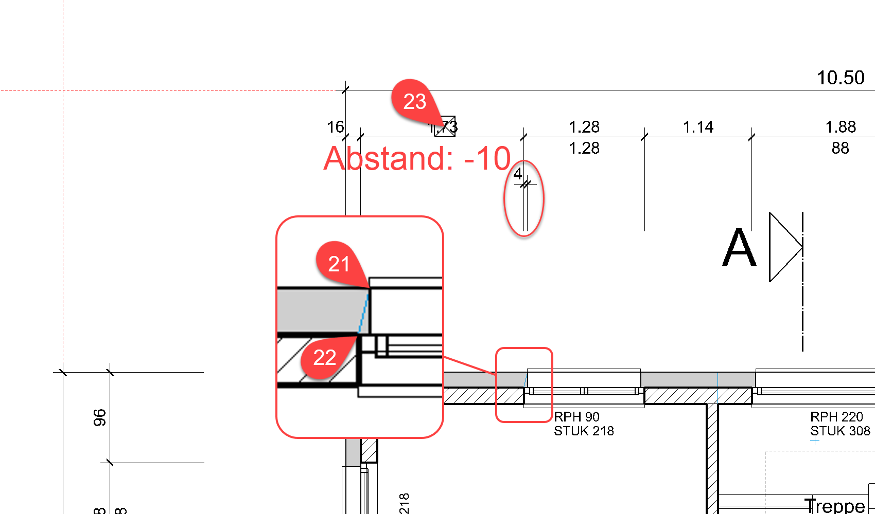
- Complete the dimensioning with a single dimension for the window's stop. Start a new dimension line.
- Change the length of the projection auxiliary-line to 10. Define the two dimension points P21 for the raw reveal P22 for the finished reveal. Set the position of the dimension line P23, to distance -10.

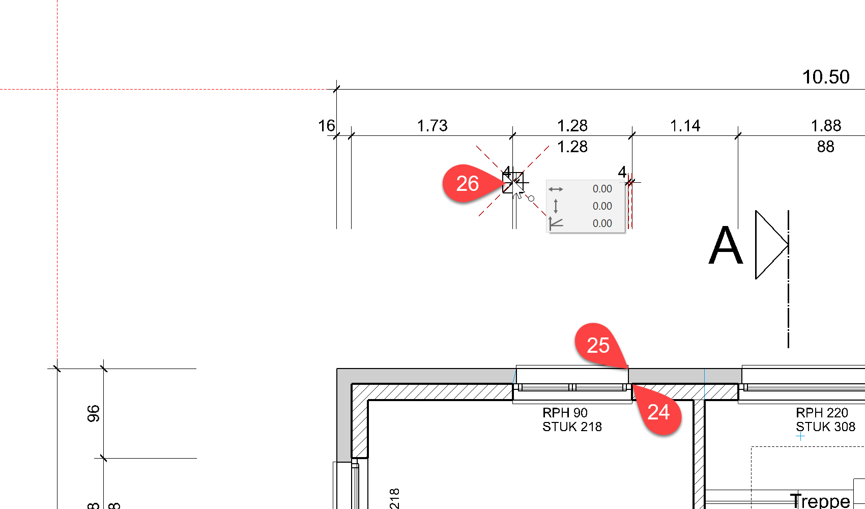
- Start a new dimension chain. Indicate the two points to be measured, P24 and P25. It is not necessary to set a distance for the position, just click on the capture point of the previously created dimension, P26.
- Now add the remaining dimensions.