Representation level
Switch representation level
To be able to plan efficiently, the modifiability of the representation level is decisive. The construction objects are drawn once and can be displayed in different ways.
The representation level does not depend on the scale of the drawing.
| Representation level: | |
|---|---|
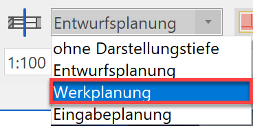
| Construction project | Working drawing |
 |
 |
In weiterer Folge wird die Landeseinstellung für Deutschland verwendet und daher können Ihre Einstellungswerte, je nach Landeseinstellung, von der in der Kurseinheit gewählten Darstellungstiefe abweichen.
Workshop
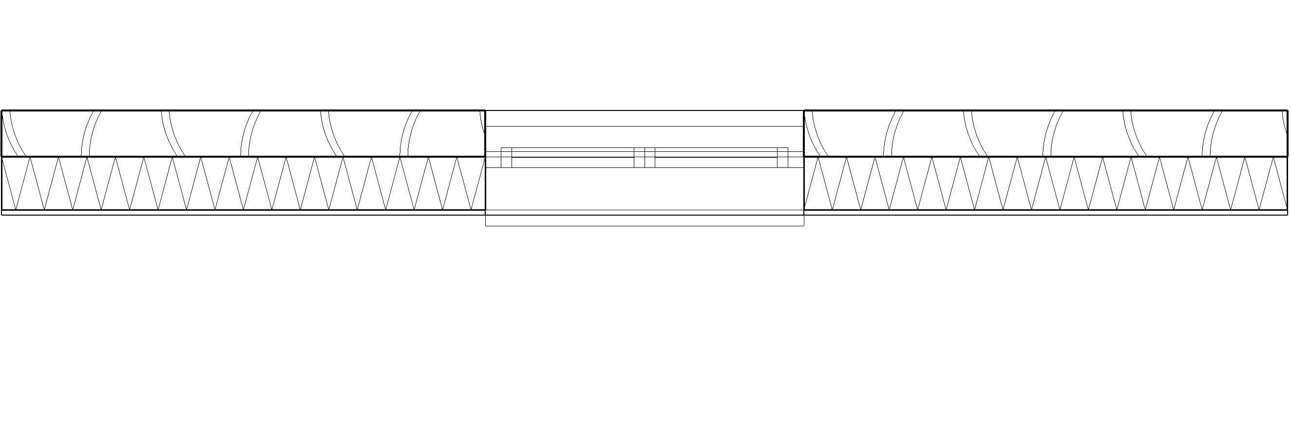
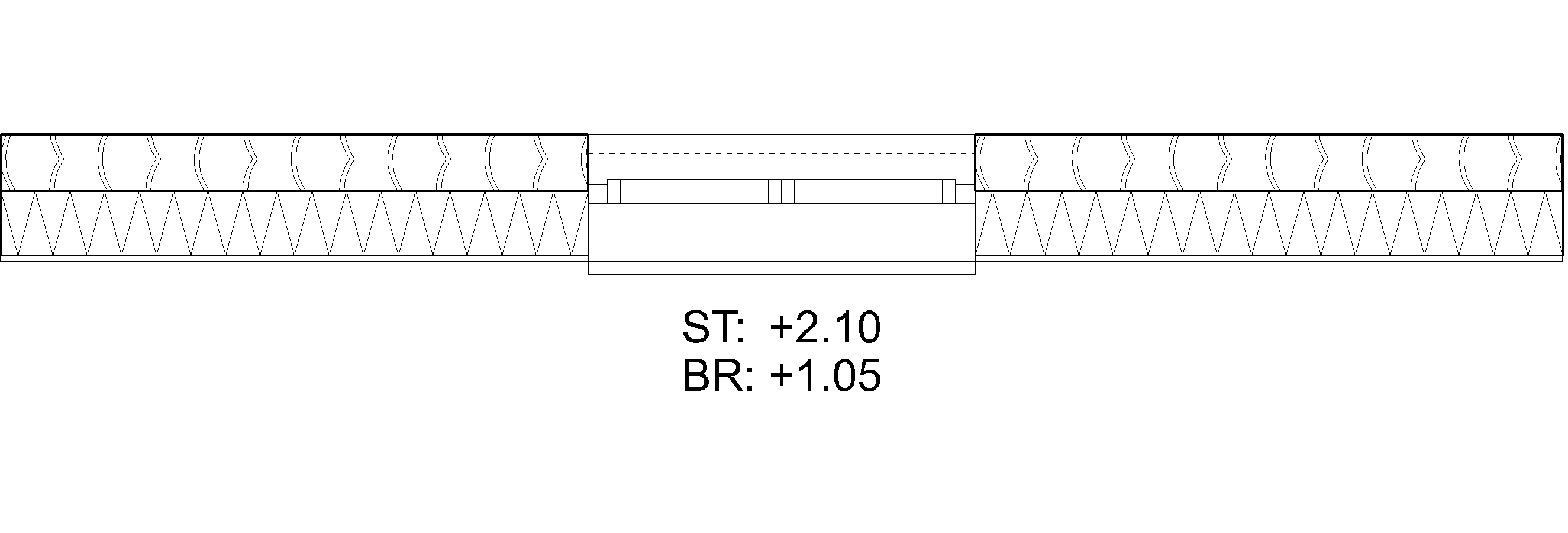
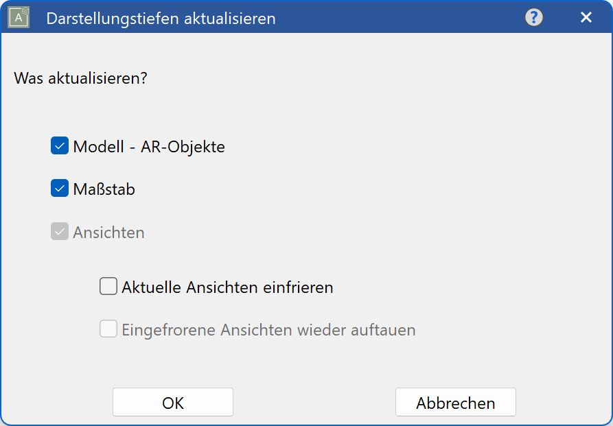
- Switch the representation level from construction project to working drawings. Ensure that you are in the model.
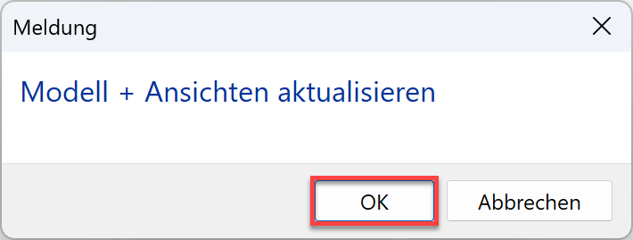
- The model and the scale must be updated.
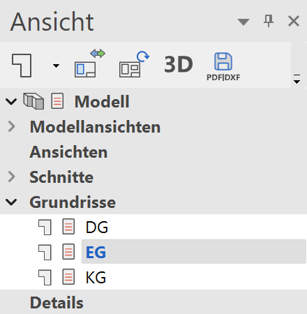
- In views manager, switch to the GF.
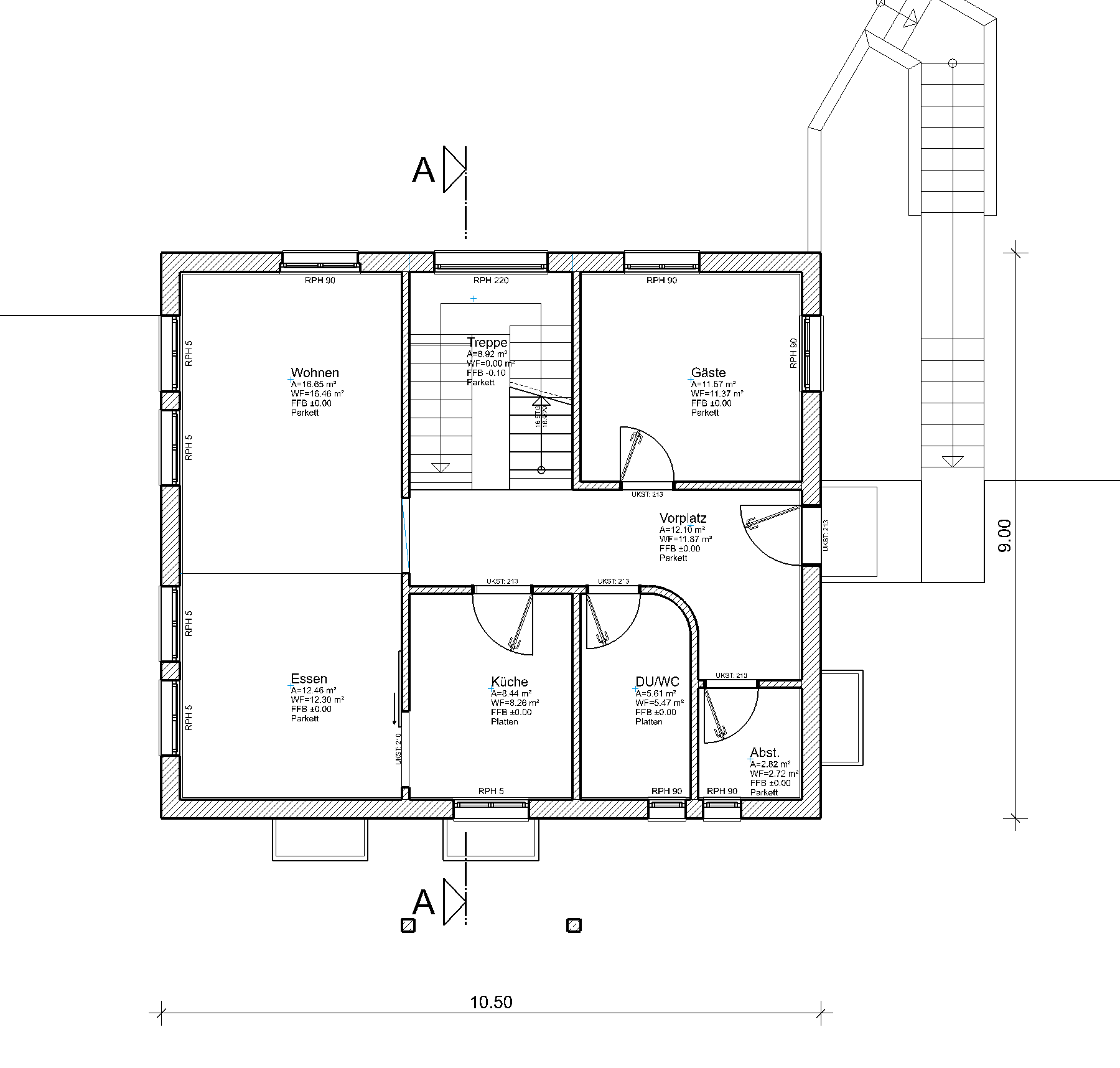
- The walls have changed the hatches; the windows, doors and room labels have adjusted the level of detail.
Representation level parameters
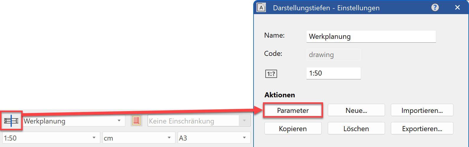
The way in which the AR objects are displayed in the different representation levels can be set in the parameter dialog.
Materials
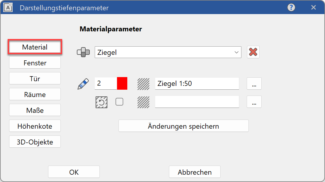
In materials manager, the line width and hatch parameters are defined which are used to display the materials of components in the floor plan view and/or section view.
Windows
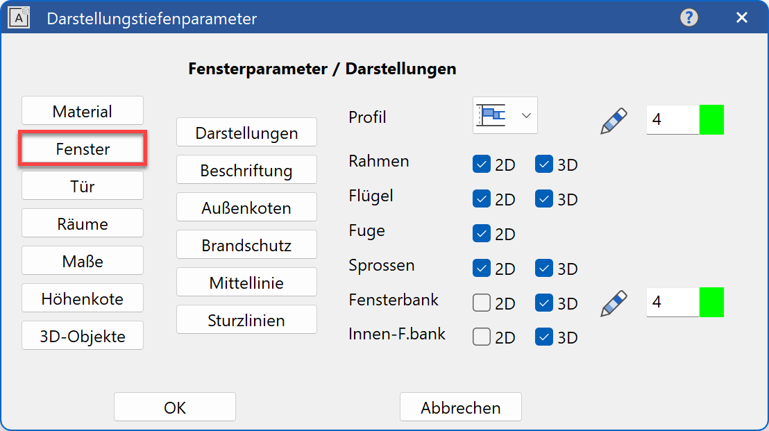
In the window parameters, the display of windows in 2D and 3D can be defined. Additionally, you can modify the type of label and the text parameters to be used, the settings of the height markers, the length and the pen for the centre line and the line types for the lintel lines.
Doors
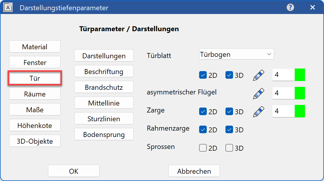
In the door parameters, you can define the display of doors in 2D and 3D. Additionally, you can modify the type of label and the text parameters to be used, the length and the pen for the centre line and the pens and line types for the lintel lines.
Rooms
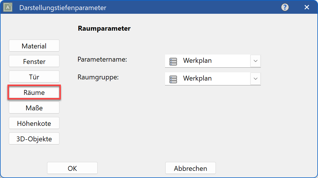
In the room parameters, you can select the data record to be used for the room labels and room groups.
Tip
The construction parts are adjusted when the representation level is changed or when the settings for this representation level are updated, even when different settings were applied on the parameter screens of the relevant construction parts. To prevent this with individual construction parts, each construction part has the option to be frozen when edited. If this option is set, this construction part is ignored when the representation level is updated.
![]()
Dimensions
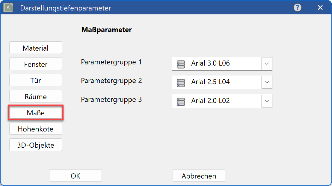
On this screen, you specify the dimension parameters for the "parameter groups 1–3" to be used during architectural dimensioning.

The dimension parameter must be selected from "...", i.e. from a list of all of the settings created under the function "Dimension parameters". The selection of a representation level automatically converts the current dimension parameter.
Height marker parameters
In this dialog window, you specify the dimension parameters for the parameter group 1-3 to be used for height markers and floor plan height markers.
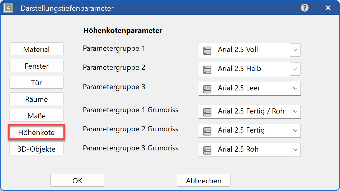
The text parameter must be selected from  , i.e. from a list of all of the settings created under the function TEXT PARAMETERS > PARAMETER NAME. Selecting a representation level automatically converts the active text parameter.
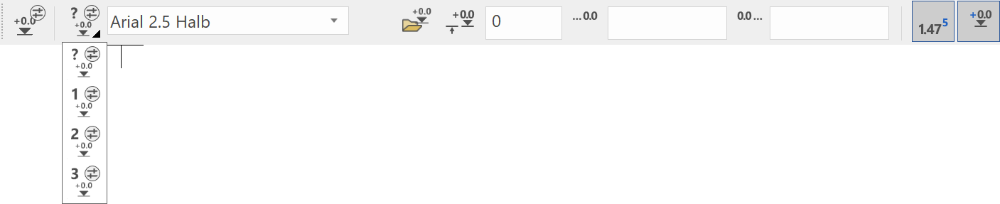
The three parameter records are linked with the parameter groups P1, P2, P3 in the height marker and floor plan height marker property bar.

3D objects
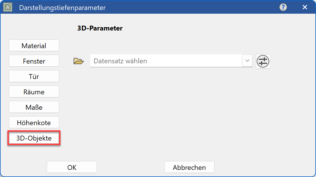
In the 3D parameters, the data record can be selected which is to be used as a standard for 3D objects (plane, box, rotation bodies, free forms, etc.).
Change representation level
After the representation level has been changed, all objects are updated (with the exception of objects on locked layers). Everything must be set up before the imaging depth is changed.
Workshop
- Switch to the model and set everything up.

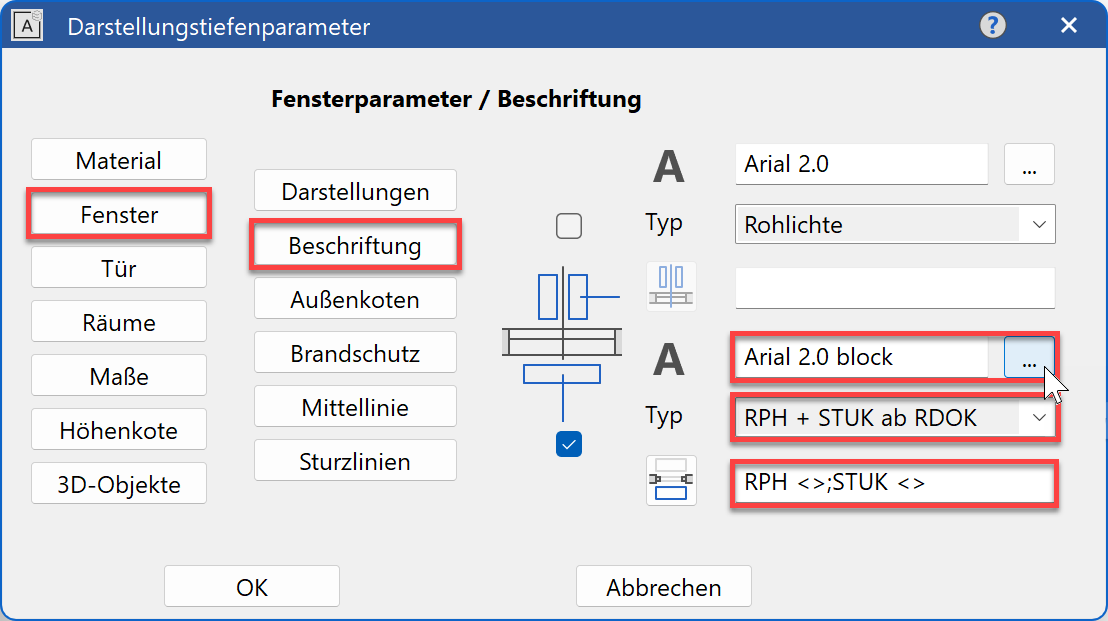
- Open the representation level settings and switch to the window parameters.

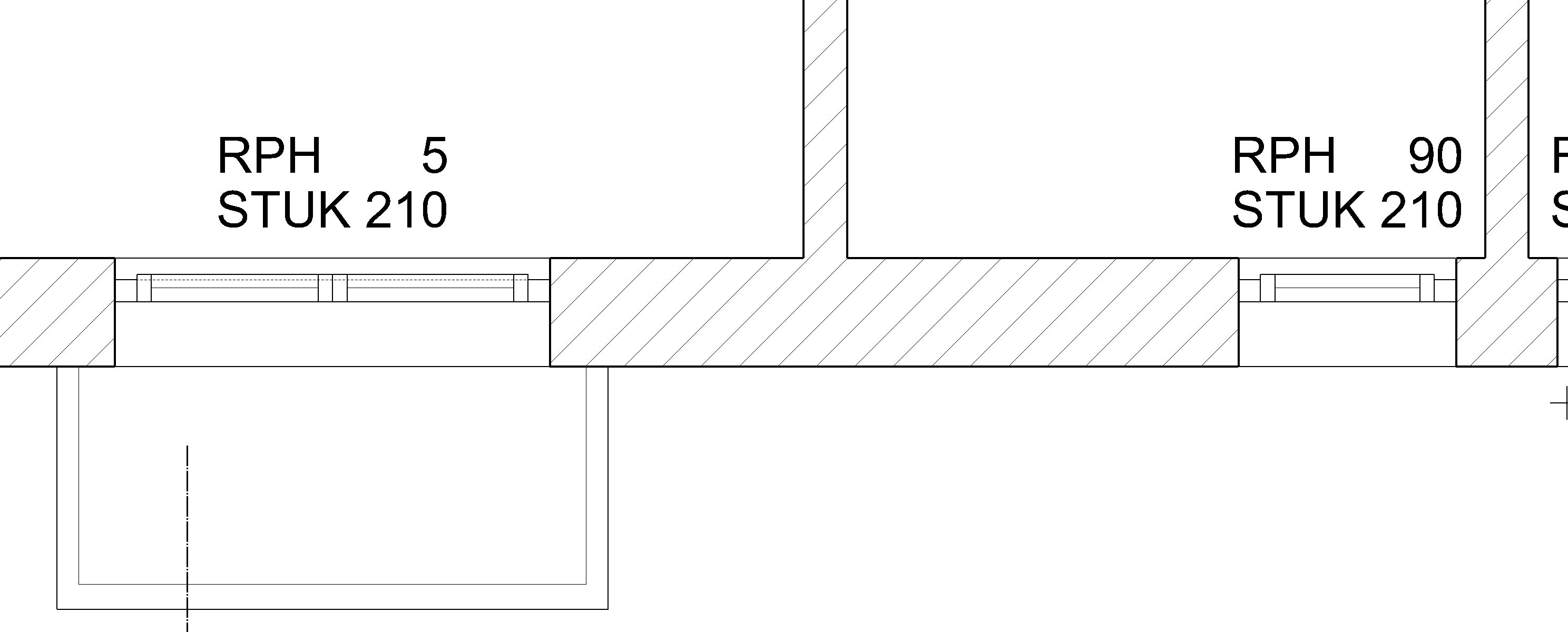
- Switch to label. Activate the inner label and change the type to “RPH + LH from TFS” (raw parapet height and lower lintel height from top face slab).
Complete the formatting text and confirm with .
.
- Update the model.
- The windows now have a label.