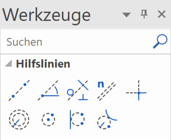
Auxiliary lines
Auxiliary lines part 1
The auxiliary lines in ELITECAD are a tool to create a secondary drawing with auxiliary lines with the help of which you can later draw a geometry.
The auxiliary lines remain with the temporary help lines that you have already learned, until you delete them.
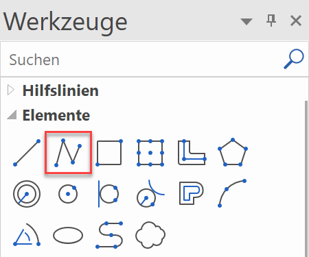
The auxiliary lines consist of lines and circles and are created using the following toolbar:
Lines / circles
Workshop
Create the following auxiliary structure with the auxiliary lines.

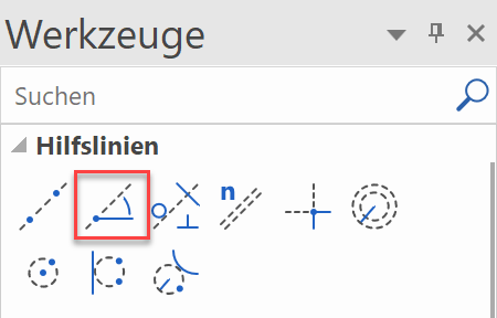
- For one horizontal and one vertical auxiliary line as a starting point, use the function STRAIGHT LINE WITH GIVEN ANGLE BY ONE POINT.

You can enter multiple angles, separated by a comma.

Click in the centre of the working area.

- The vertical auxiliary lines have 4 times the gap of 200 cm. Select the function PARALLEL LINES.

Set distance 200 and 4 copies.

Click NEXT to the line to which the help lines are to be created. Depending on whether the vertical or the horizontal auxiliary line is closer when you click, the lines will be created accordingly.


- The horizontal auxiliary lines have different gaps. They can be created one after the other or all gaps can be created together at once, separated by a comma. Do not forget to reset the number to 1.

Click above the horizontal auxiliary line, which can lie quite a bit outside, so that a vertical help line is not suddenly closer when you click.


- The next auxiliary line has an angle of 35°. Access the function STRAIGHT LINE WITH GIVEN ANGLE BY ONE POINT and set the angle.


- The next help line is perpendicular to the 35° slanting auxiliary line just created. Access the function TANGENT NORMAL ON LINE.

First, determine through which point the auxiliary line is to pass and then to which line it should be perpendicular.
Through which point?


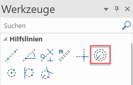
- The final auxiliary line is an auxiliary circle. The circle must be at a tangent to a line and pass through two additional points. Start the function CIRCLE BY 3 POINTS OR TANGENTS.

Tangential to the first vertical auxiliary line

1st point

2nd point

- In the auxiliary geometry draw a polygon. The intersection points of the auxiliary construction can now be captured easily.
DRAW function

Start at point P1 and draw until point P7.

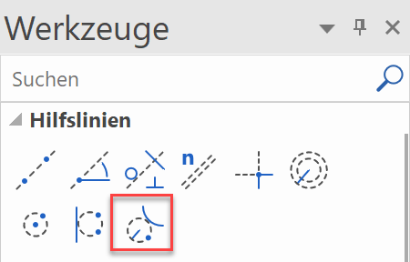
The curve is next: Use the Tab key to show the input assistant and select the function CURVE OVER 3 POINTS.
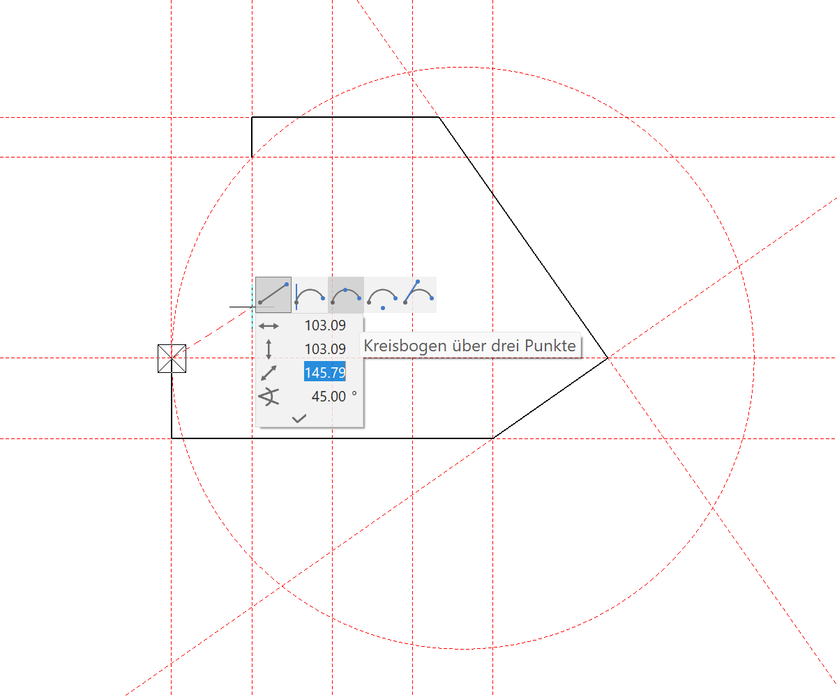
Set P8 mid-way along the auxiliary line and P9 on the end point.


An external wall, a slab or a structure could now be created from this polygon.

- To delete all help lines, select the function DELETE ALL AUXILIARY-GEOMETRY.


- To remove the auxiliary lines from the screen, open a new file.

Auxiliary lines part 2
Now the following example is to be constructed in which all functions from the first part of the course unit are used.
Draw auxiliary lines to define the outline of the belt.
With the PARALLEL LINES function, a vertical and horizontal auxiliary line is always automatically placed through the origin of the CAD 0 point.

Before starting to draw, various settings are made.
Scale 1:1, units mm and format A4

Tip
ATTENTION: If auxiliary lines or auxiliary circles are already available, NO lines are placed through the CAD 0 point.
Workshop
- Create vertical guides with distance 60.
- Fill in the property bar with the gap of 60 with 1 repetition.

- Specify the point P1 to create the vertical parallel.
- Now enter the distance 50 for the horizontal auxiliary line in the property bar and set the point P2.


Auxiliary circles and lines
Workshop
- Create 2 auxiliary circles with the radii of 20 and 10.
- Enter the radius 20 into the property bar.

- Set the capture mode to AUTO SNAP and set the point P1.

- Change the value for Radius on the property bar to 10 and set the point P2.

Tip
The intersection of the auxiliary line is automatically recognized by the AUTO SNAP function. Just tap near the intersection point so that you can see that the snap point is searched for automatically.
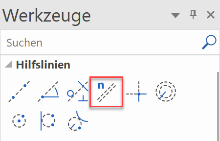
- Create the auxiliary line by specifying the angle.
- Enter the angle 40 into the property bar.

- Place the line on point P3.
- Change the value for angle on the property bar to 10 and set the point P4.

- Now enter an auxiliary circle again, but this time with the CIRCLE BY RADIUS function.
- Enter the radius 20 into the property bar.

- Place the auxiliary circle by entering points P5 and P6.

- Now the tangent between the two circles is determined.
- Place the cursor at point P7 and point P8.

Delete
For a better overview, now delete the auxiliary lines that are not required.
Workshop
- Click on the desired auxiliary line (it will be highlighted magenta) point P1, and remove it with the Del key or with the icon
 (delete). (With the Shift key a selection of several auxiliary lines is possible). Now the dialog box appears with the query, Delete selection? This is confirmed with Yes.

- For the remaining auxiliary lines that are not required, proceed as described above.
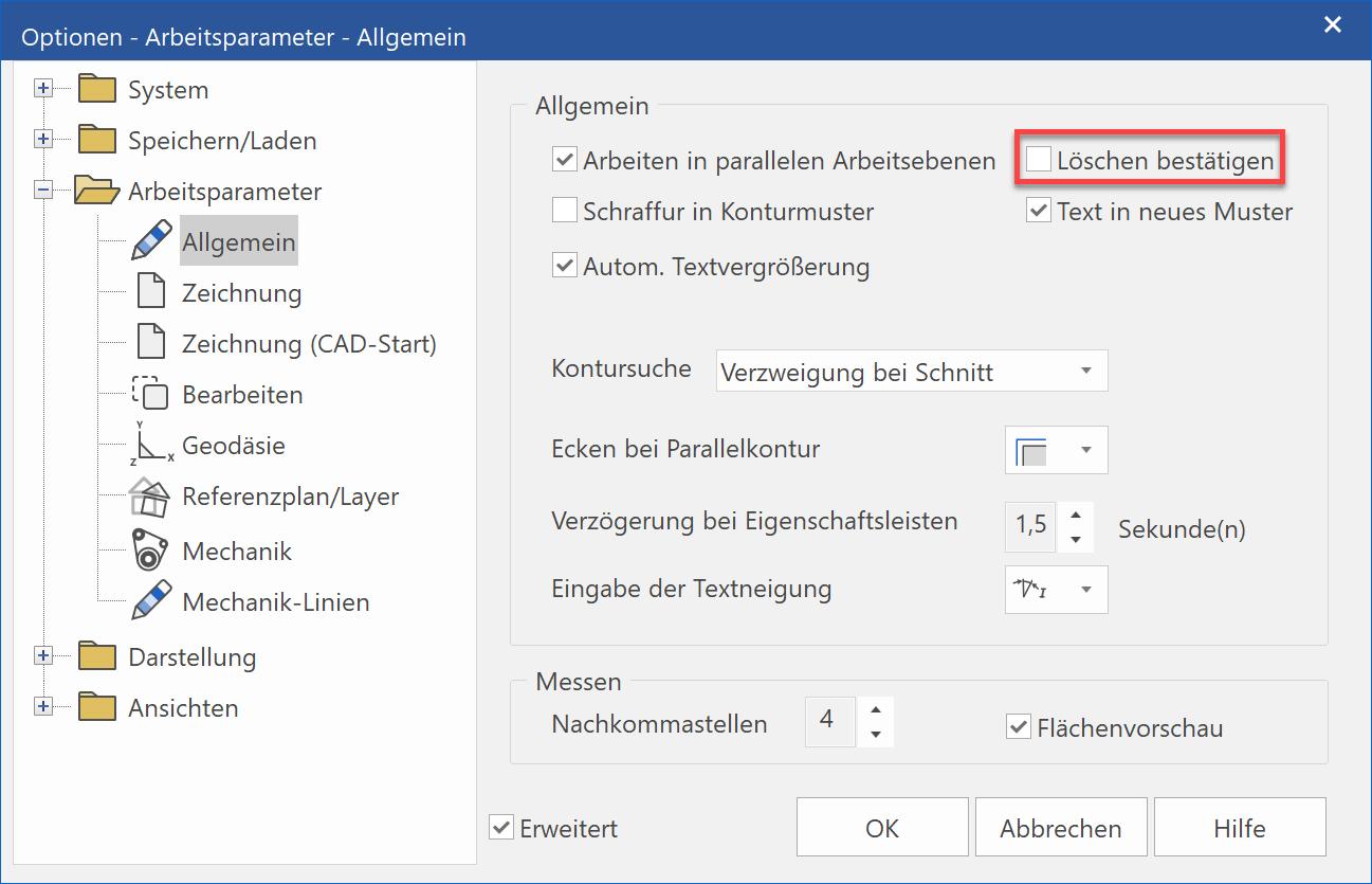
Tip
So that the query Delete selection? does not appear when deleting and you can therefore work more quickly, the following can be set:
SETTINGS > OPTIONS > WORK PARAMETERS > GENERAL and then deactivate the button Confirm delete.
Draw
In the next step, you will learn to draw out the auxiliary lines.
Workshop
- Select the function DRAW.
The property bar will be displayed. - Select the "continuous" line type and the colour selection “2” (red).

- Enter points P1 - P7 using the auto snap. Pay attention to the correct cursor arrow position for the circular arcs.

Tip
When first starting out, you can use the zoom command to enlarge situations in order to better recognize the snap points. Later, when there is more routine, this will no longer be necessary.
-
To end the line sequence, press the Esc key or select the CANCEL function
 .
.
- Save work copy!
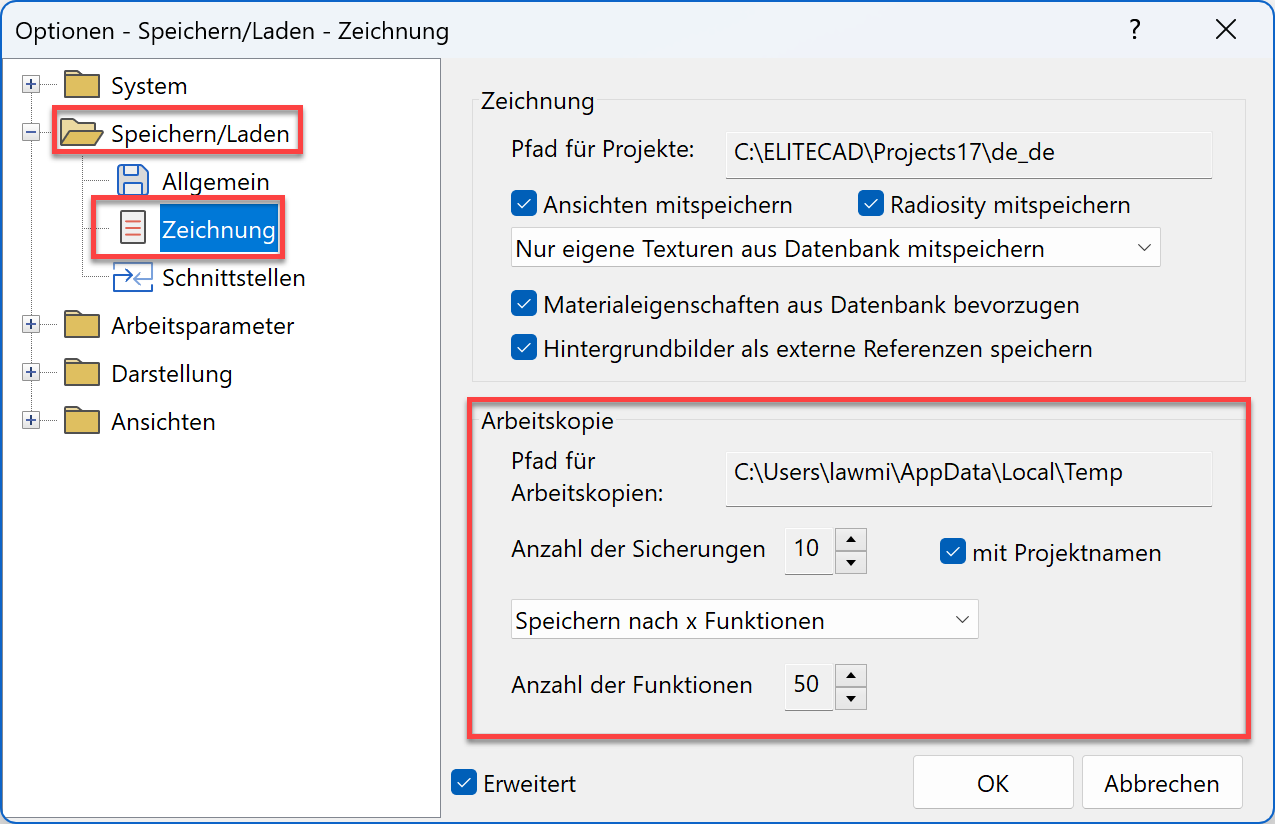
Work copy
The current stage of work is saved to a temporary directory. A work copy is stored under the name "woco". A certain number of work copies can be made whereby the oldest one in each case is removed and the new one becomes "woco_0".
A work copy is nicht to be used to save the final version of a project!
Save work copy
![]() or with the key combination Ctrl+W
or with the key combination Ctrl+W
Load work copy
![]()
Opens the last work copy (woco_0).
To load an earlier work copy, select the function LOAD WORK COPY in the FILE menu.
Menu FILE > LOAD WORK COPY
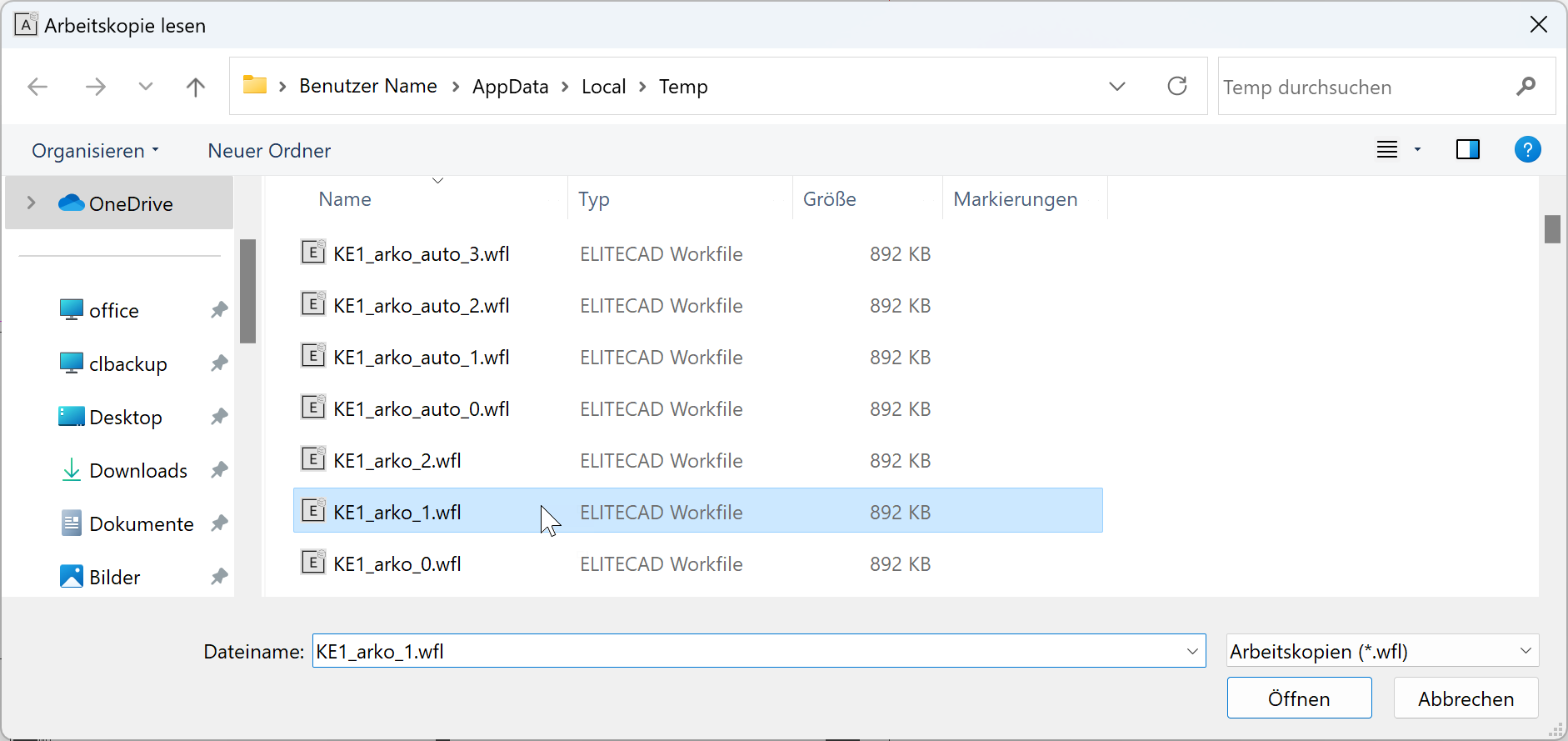
Select the desired woco and click OPEN to import it into the CAD.
All of the settings in connection with work copies can be found in the options.
Menu SETTINGS > OPTIONS > SAVE/LOAD > DRAWING