User interface
Launch program
Workshop
- Launch the program.
ELITECAD ME17 icon is located on the Desktop.

Double-click on the icon
- ELITECAD launches and initializes the different components.

User interface
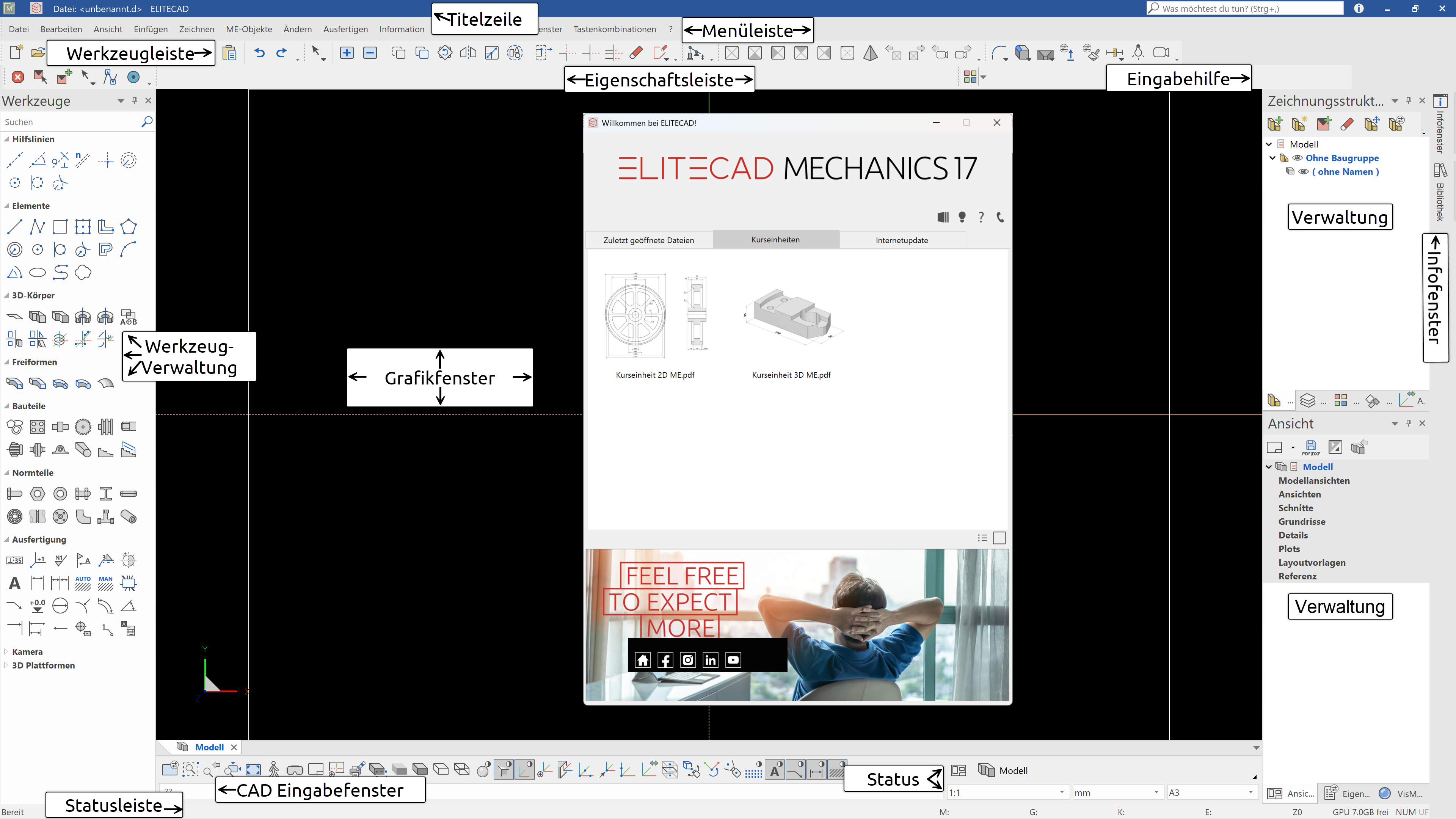
The appearance of the user interface can vary, depending on the installation and screen resolution.
Title line

The title line of the program shows, which project is loaded, in which structure and storey you are currently located, and which file is open. Furthermore, there is an icon for the welcome window ![]() and the status of the info window
and the status of the info window ![]() is also available including the number of current messages.
is also available including the number of current messages.
Function assistant

Functions can be searched for and also started in this text field. All functions that contain the entered character string are offered for selection.
Menu bar
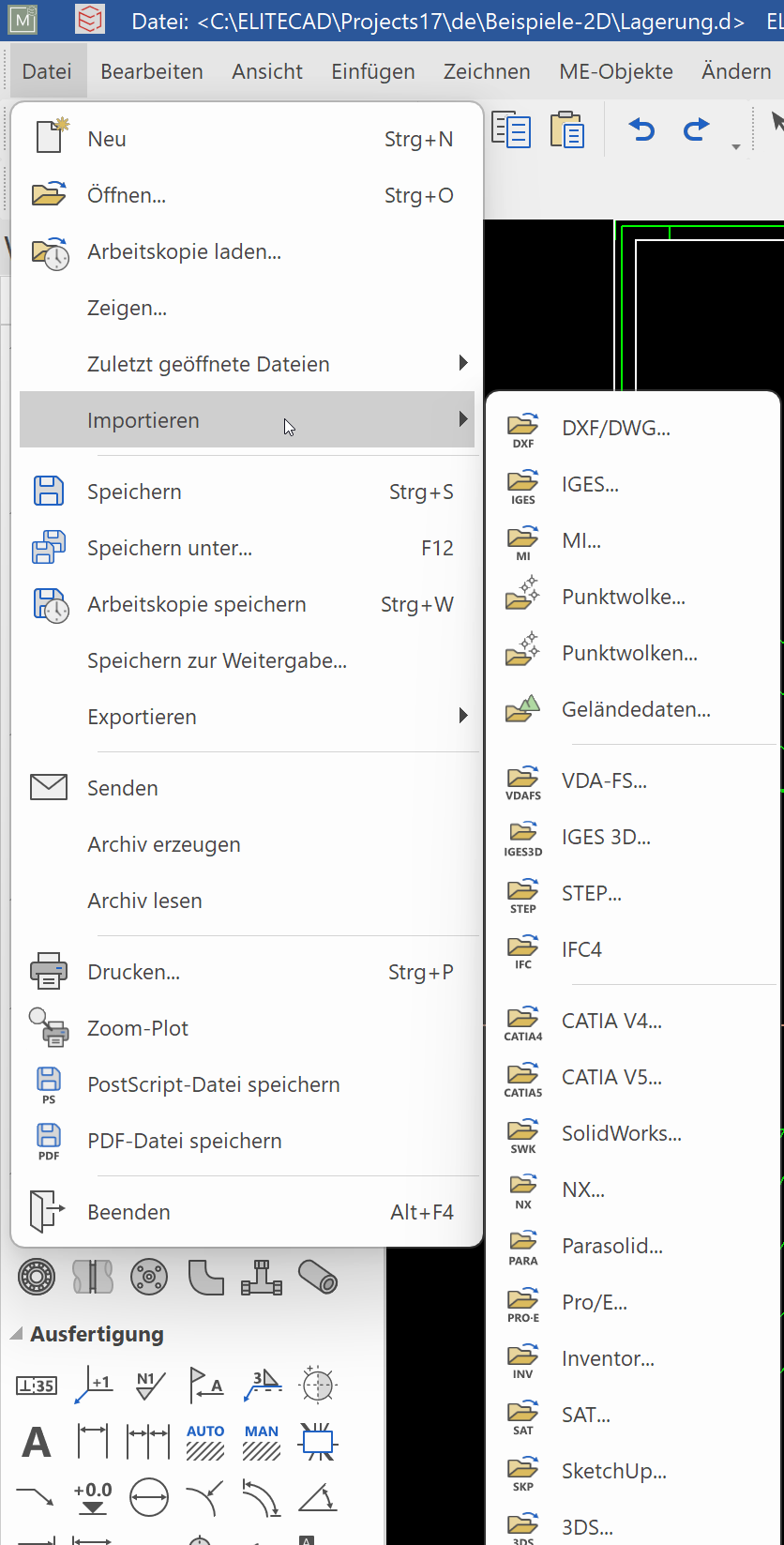
The menu bar with opened and extended "File" menu. Here the submenu “import” is opened.
Toolbars
![]()
Toolbars offer rapid access to the most important commands. Many of the symbols or icons can also be found with the same meaning in the relevant menu entries.
Tools manager
In the tools manager, you will find a number of different toolbars combined. These can be expanded and minimised to suit your requirements, enabling you to bring together a number of functions in a small space. The order in which the bars appear can be changed and you may also add your own new bars.
Property bar

The property bar displays the properties of the active part or for a manipulation to be performed. There are property bars for manipulations, elements, hatch patterns, dimensions, text, 3D solids and components. The example shows the property bar of a circle.
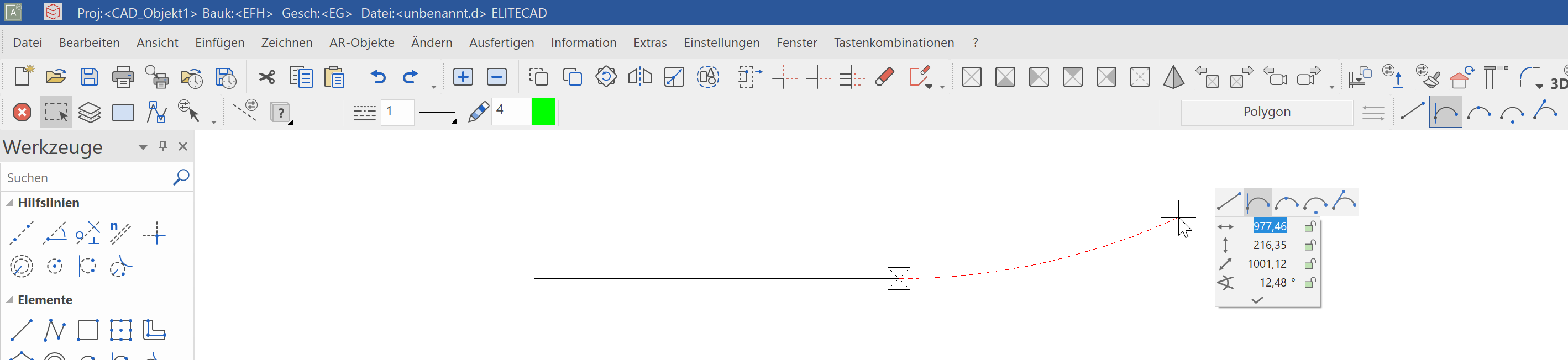
Input assistant
The input assistant consists of additional functions that vary according to the function selected. The functions for the input assistant can also be displayed on the cursor using the Tab key.
Not every function has these extended functions. In principle, these are the create functions and the manipulations on the handle.
Example of the polygon drawing functions for drawing a curve:
Example of manipulations on the handle of a polygon:

CAD input window

The input window contains the image properties, the information line, the input line and the status.
Image properties

These commands are fixed. They control how the data is displayed on screen. Zoom factor, cut-out, imaging, etc.
Information line
This line contains commands as to what you must enter or determine within a function.
Input line
You use the input line to forward information to the program. This information could be texts, coordinates or, in event of prompts, confirmations.
Status window
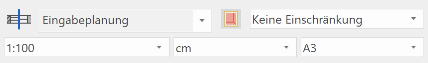
Here you can select representation mode, scale, units and the page format.
Status bar

The status line is the lowest line of the program. The left-hand area shows confirmations that e.g. the work copy was saved successfully.
If working with classification is active, then the classification (model, group, class, level) from the active object is displayed in the status bar.
The current position of the working plane is shown on the right. If no changes have yet been made, the value "Z0" is displayed. "Z" stands for the axis, "0" indicates the height on this axis.
Views manager
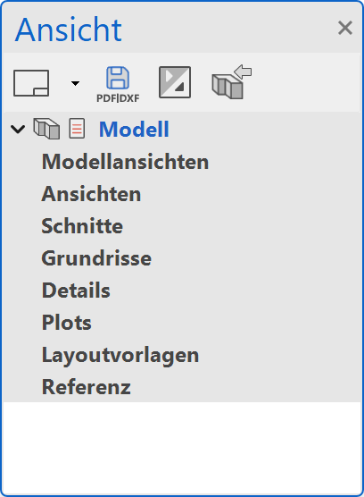
In complex projects, managing the various drawings and views is a key issue. This manager becomes even more interesting if it should also include dependencies. Thanks to the drag & drop technology in ELITECAD, it is possible to handle almost any number of views with their dependencies very intuitively.
More about the View manager
Classification
ELITECAD uses the very powerful and extensive classification with models, groups, classes and levels. This arrangement can be used extremely productively, but requires intensive discussion on the part of the user.
More about the Classification manager
Layer manager
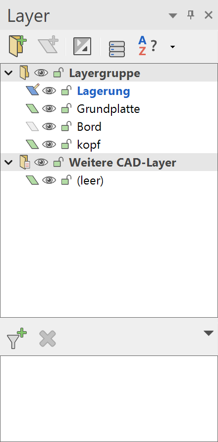
The layers are an additional simple linear structure.
Projects can now be processed with both structures (Classifications and Layers) in parallel, so that users can choose either one or the other structure.
More about the Layer manager
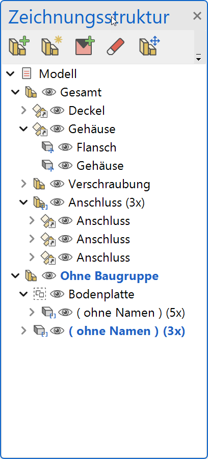
Drawing structure
In addition to the layer and classification, an ELITECAD drawing can also be structured hierarchically with the help of assemblies. An assembly defines a combination of ELITECAD components (models and objects) into a logical unit.
A component can be a single model or an object that is composed of several models. Objects are especially 3D objects that are created using several models (e.g .: 2 view bodies, Boolean operations).
An assembly can also have sub-assemblies. Thus, a structure tree can be formed, the depth of which is arbitrary.
The top assemblies are also known as main assemblies.
If a new assembly is created, it must be assigned a unique name. If this is not the case, a number is automatically added to the name at the end.
More about the Drawing structure manager
Infofenster
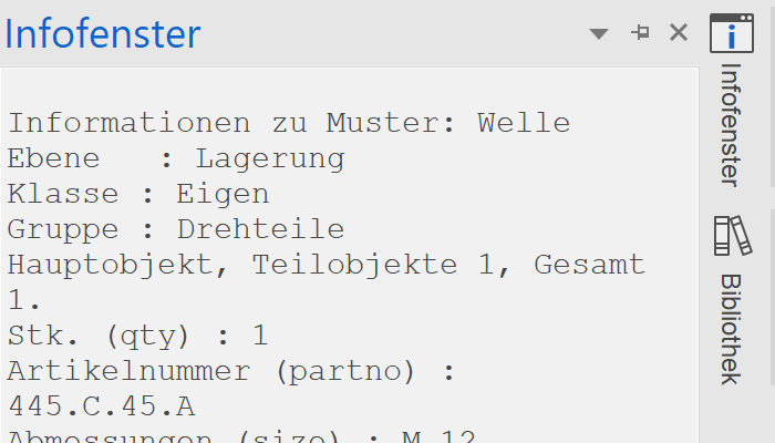
The info window shows information, such as, the listing of element values, sizes, or messages during data import.
A double click on the Info window bring it into to foreground.
Info balloon
The messages of the info window can also be displayed in the info area (task bar) of the operating system.
Pre-condition: Activated option "Show notifications as info balloon" in ELITECAD Menu Settings > Options > System > User interface
Drawing lines
The basic functions for drawing lines are the individual line, the polygon and the rectangle.
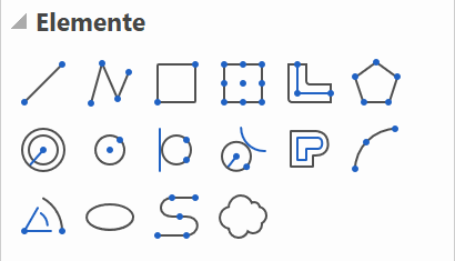
When you select one of these functions, the property bar for the element appears.

The line is composed of the line and pen type.
Line types
There are 9 "fixed" line types available. Other additional line types can also be defined.

Pen types
You can choose from 1024 differently coloured pen types. The selection opens with a single click on the colour square. There are different colour squares sorted by pen number, colour values or grey values.
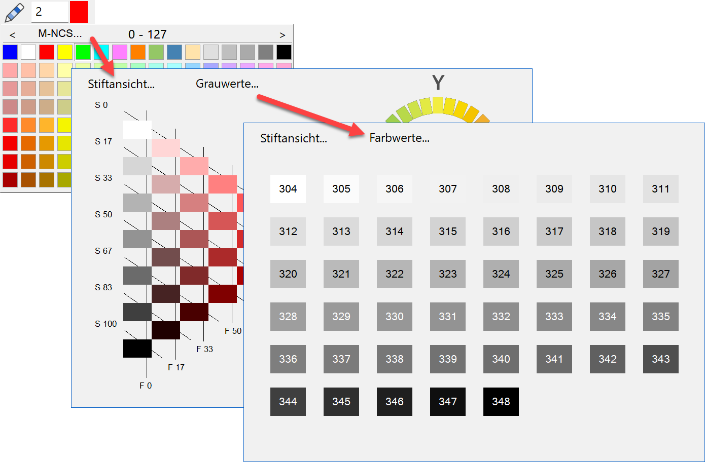
The line appears in the relevant colour on the screen. A pen thickness is assigned to every pen colour.
In the colour properties the screen colour, print colour and pen thickness per pen number can be adjusted. If you are not yet familiar with the pen numbers and the corresponding pen thickness, you open the screen by selecting SETTINGS > COLOUR PROPERTIES from the menu.
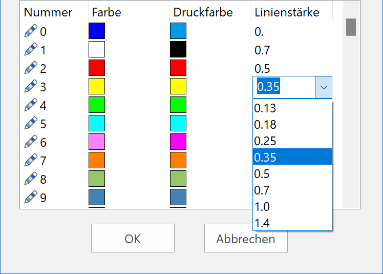
Note
Pen 0 is only displayed on the screen; these lines do not appear on the printout.
Cursor
The cursor may appear as a marker, a crosshair, an arrow and, if a point is entered, have a value field as well. The marker always specifies the last position. As soon as the cursor is at right angles to the last position, temporary reference lines appear and display the angle. This means you can check whether you are drawing at right angles.
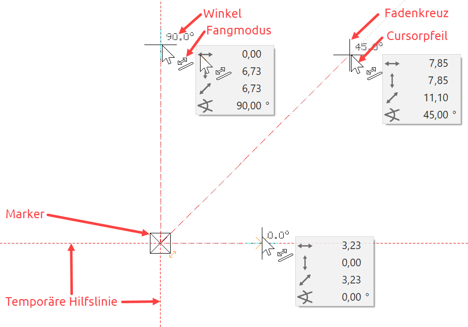
The cursor responds as soon as it is positioned near a capture point and indicates the type of capture point by means of a symbol.

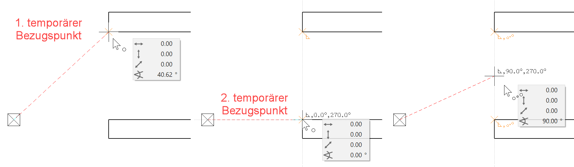
Temporary reference points and help lines
When you are drawing, references often need to be made to the geometry that has already been created.
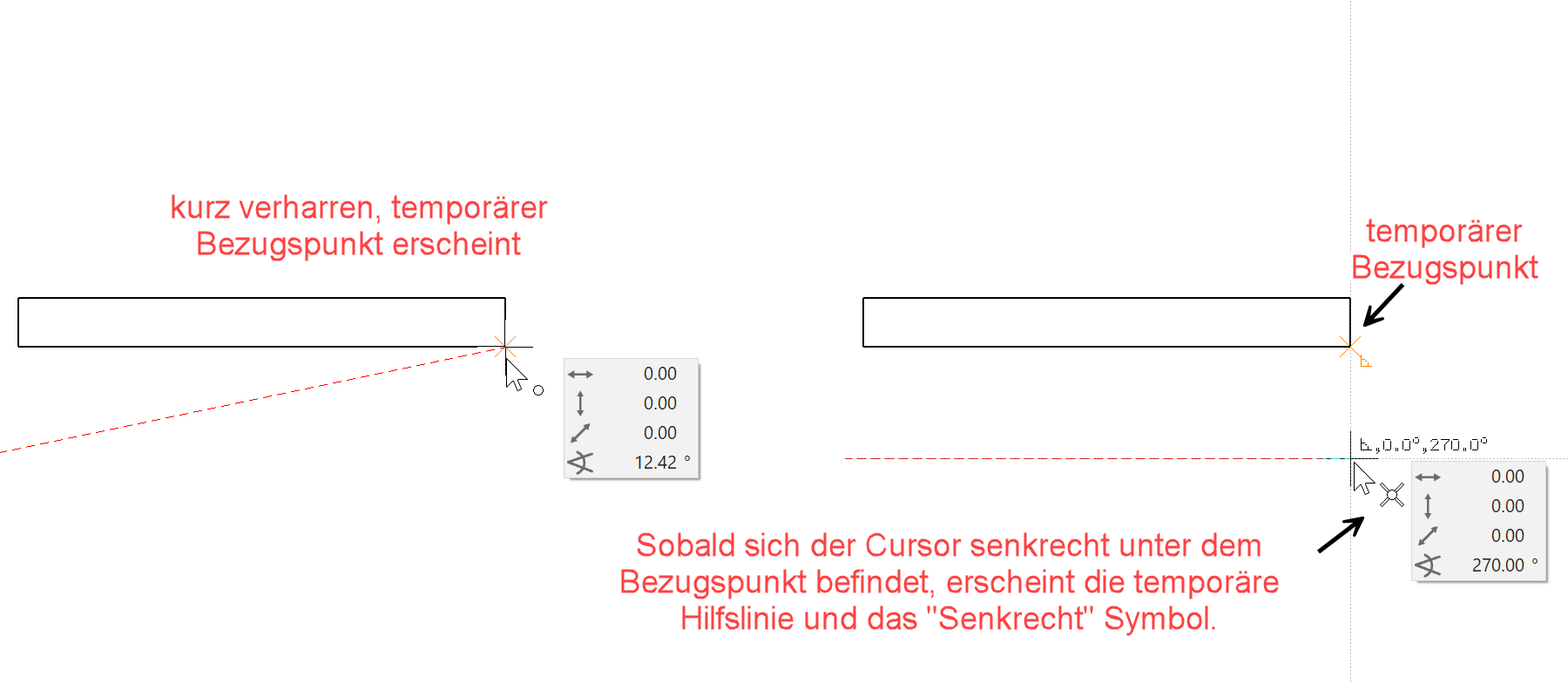
You create a reference point by hovering the cursor briefly over the desired point; the program displays the reference point as an orange cross.
Instead of hovering over the point, you can press the Shift key.
The temporary reference points are deleted again after every click. The points can be deleted manually the same way they were created.
Drag the line until it is perpendicular beneath a wall corner:
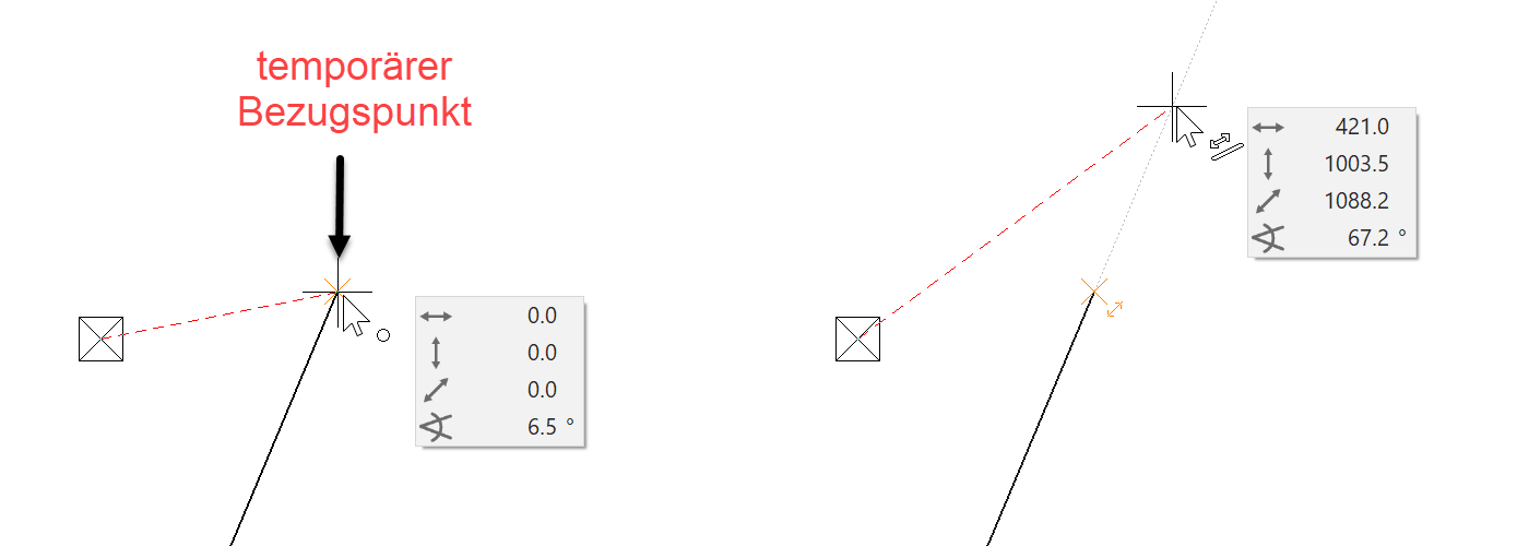
Drag line into the extension of an existing line:
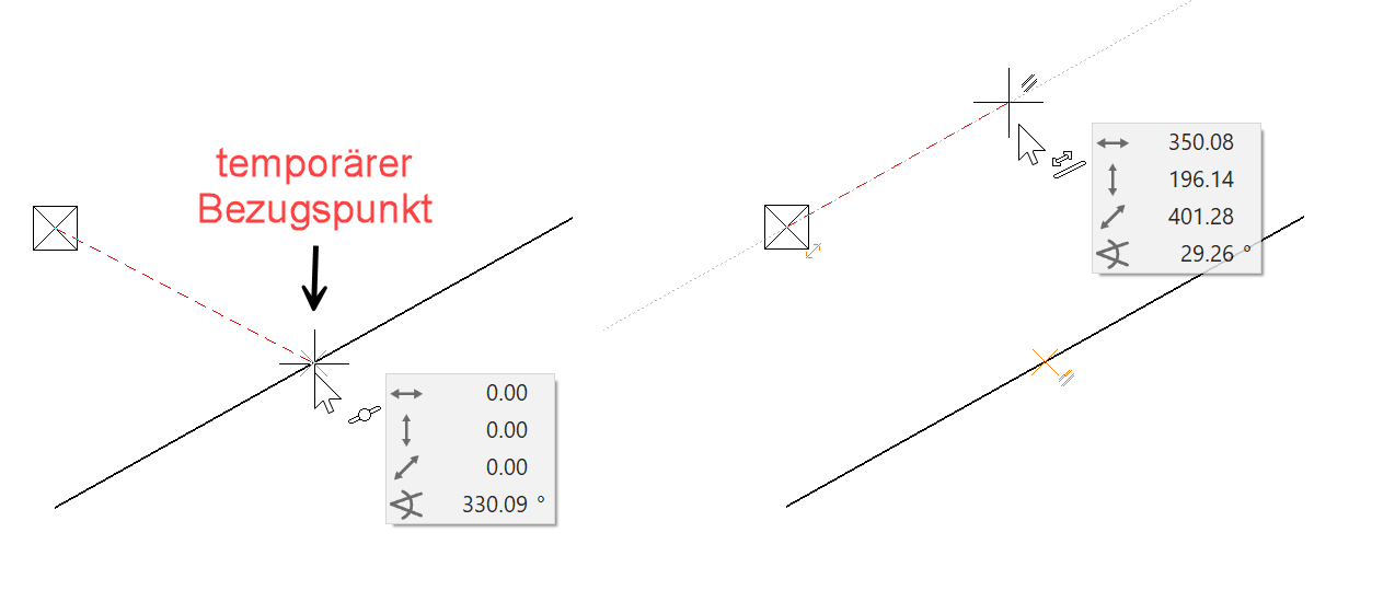
 A new line/auxiliary-line must lie parallel to an existing line/auxiliary line:
Draw a line in the middle of two points:
Note
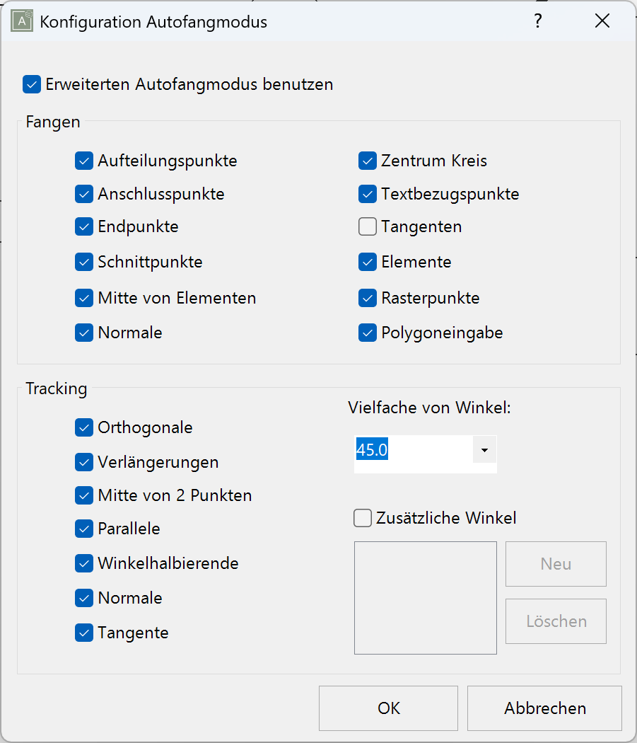
If, when drawing, no temporary help lines or reference points appear, this means the functionality has been deactivated or changed in the configuration settings of the autosnap mode.
Configuration of autosnap mode:
Right-click > Configure autosnap…
Rotate, zoom and move an image
Move the image
Simultaneously hold down Ctrl + middle mouse button and move the mouse or, while holding down the Ctrl key, use the arrow keys on the keyboard ↑ ↓ ← →.
Rotate the image in 3D
If you just keep the middle mouse button pressed and move the mouse, you will turn in 3D. In the 2D version, this is not possible in the standard settings.
Moving the mouse creates the matching movements on the screen.
Reset camera
![]()
Select this function to return a rotated screen to its original position. Starting position means "view normal to the work plane" and "page format centred on screen".
The key combination Ctrl+Space will also reset a rotated work plane to its original flat position.
Zoom on the image
Simultaneously press the Shift key and centre mouse button and move the mouse up to zoom in on the image and down to zoom out.
If the centre mouse button is a scroll wheel, this can also be used to zoom.
The zoom function applies to the current cursor position.
Tip
Should you wish to retain the current work plane and merely zoom onto the format, you can do so using the function ZOOM ON FORMAT. ![]()
Zoom by 2 Points
![]()
Here you specify two points (P1, P2) over a diagonal. This area is then zoomed and displayed on the screen.

Image displays
| Wire model | Pixel hidden line | Solid model | Edges |
|---|---|---|---|
| Ctrl+D | Ctrl+H | Ctrl+D | Ctrl+K |
 |
 |
 |