Bend
Workshop
- Start NEW MODEL. (e.g.: "bk, plate, bend")

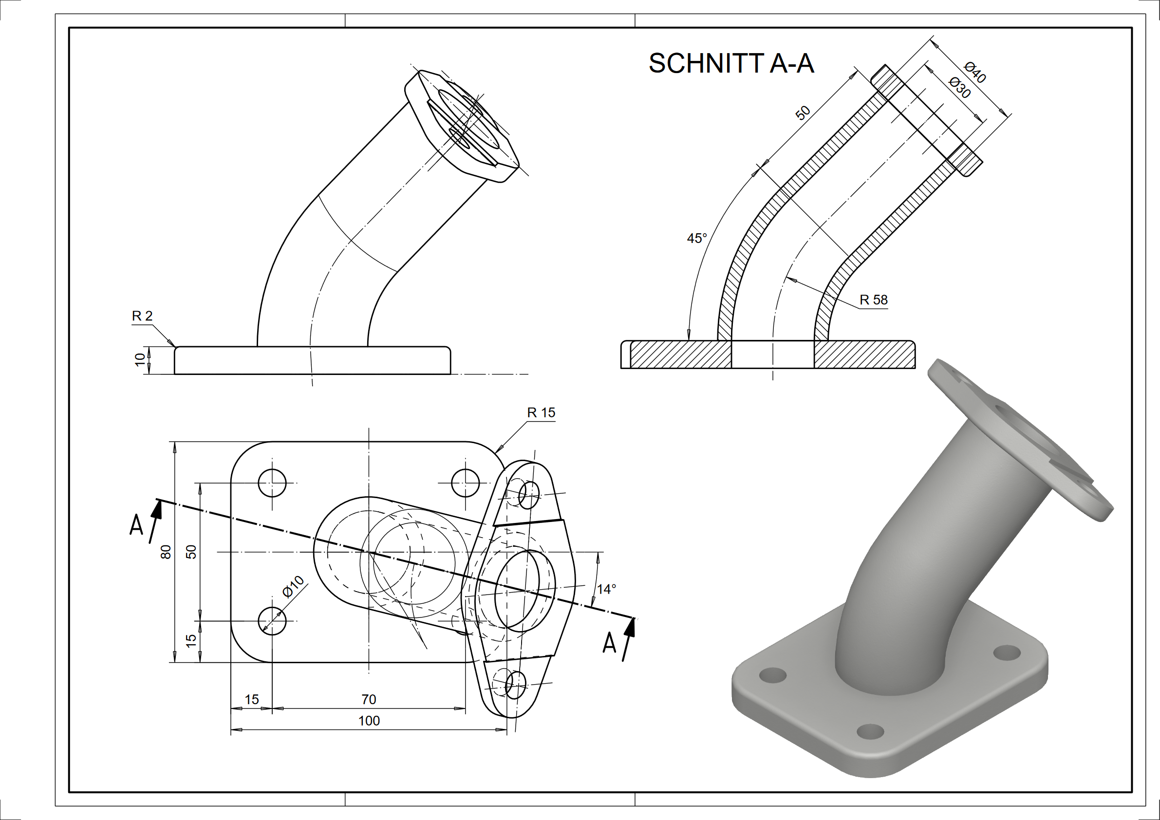
- Draw the plate contour (including circles for holes) and define it as a box.
(height 1 = 0; height 2 = 10)

- Select EDGE BLEND.

Please select definition
Click on the top of the panel, near the outside edge.
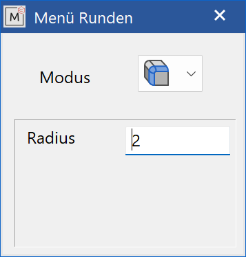
Fillet the lower edge with a radius of 2 mm.

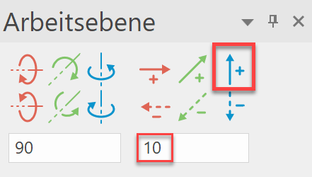
- Move the work plane upwards by 10 mm. (CHANGE WORK PLANE)

- Start NEW MODEL. (e.g.: "bk, pipe1, bend")
- Draw two circles with a radius of 15 mm and 20 mm in the centre (origin) and then define them as a rotation box. (DEFINE ROTATION BOX)
Set the start angle to 0 and the end angle to 45.
Please click point 1 of rotation axis for new contour
input a-14,d58. (P1)
Please click point 2 of rotation axis for new contour
input a76,d10. (P2)

Tip
The axis of rotation can also be indicated by pre-drawn geometry auxiliary lines.
- Select WORK PLANE ON SURFACE and tap the top surface of the pipe. Then SELECT WORK PLANE ORIGIN and use the CIRCLE CENTRE snap mode to set the origin in the pipe centre.


- Start NEW MODEL. (e.g.: "bk, pipe2, bend")
- Draw two circles with a radius of 15 mm and 20 mm in the centre (origin) and then define them as a box.
(height 1 = 0; height 2 = 50)

- Select SELECT WORK PLANE ORIGIN and set the origin in the upper pipe centre using the CIRCLE CENTRE snap mode.

- Use INSERT > POSITION… to load the previously created drawing "bend_k.d" and position it at the origin.
(Ctrl+1) = (X0, Y0)

The entire assembly can now be saved.