Bolt

Workshop
- Start NEW MODEL (e.g.: "bk1, bolt")

- Draw the following contour in the top view.

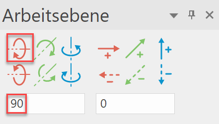
- Rotate the work plane about the X-axis with 90°.

- Now draw the following second contour.

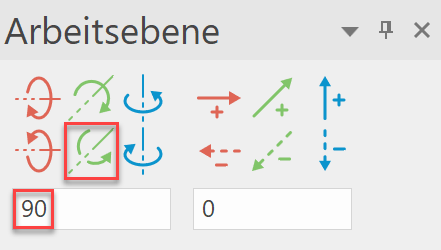
- Rotate the work plane about the Y-axis with 90°.
- Now draw a circle with a radius of 20 mm.

- Now create a 3D volume with DEFINE 3-VIEWS OBJECT.
Tip
With 3-view object (3VO), the contours must be closed and drawn in different work planes.
The centre line must be its own model!
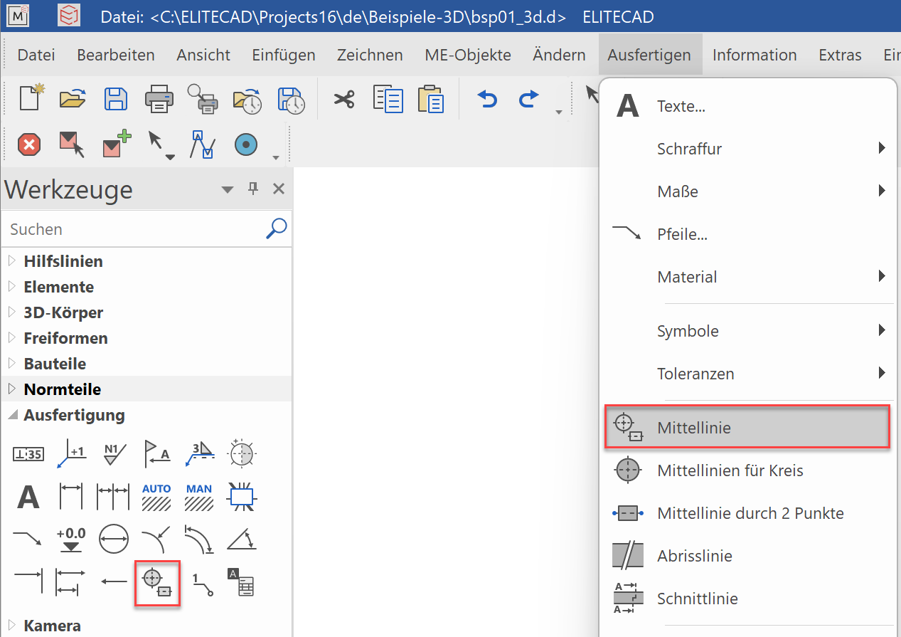
The centre lines can be created from LAY OUT> CENTER LINE or CENTER LINES FOR CIRCLE.
Tip
If the center lines were created with the mechanical functions (LAY OUT > CENTRE LINE or CENTRE LINES FOR CIRCLE), they appear automatically in the 2D plan.
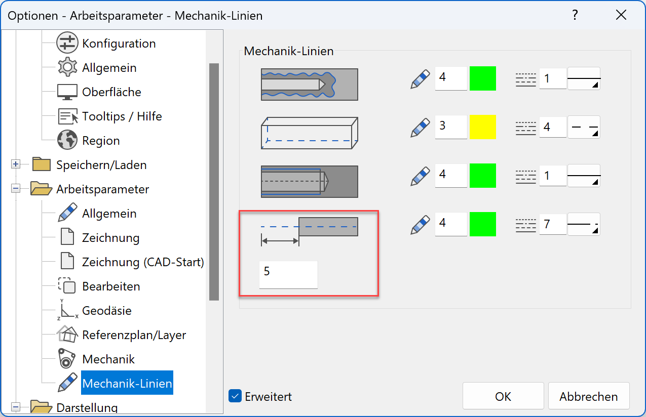
The excess length of the centre lines can be configured in SETTINGS> OPTIONS> WORK PARAMETERS> MECHANICAL LINES.
Tip
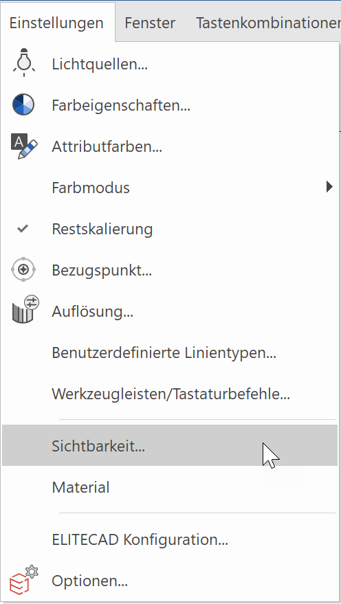
If centre lines or other contours in the 3D model are not entered with the mechanical functions, they must still be edited in SETTINGS> VISIBILITY.
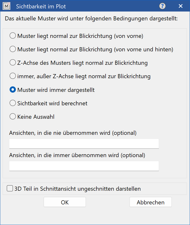
e.g .: start NEW MODEL and draw 2D centre line. If "MODEL IS ALWAYS DISPLAYED" is selected, this centre line appears in all views in the plot.
With the SHOW 3D OBJECT UNCUT IN SECTION VIEW, it can be determined which part (bolts, screws, ...) is shown uncut.
(Screws that were created with a DIN module from ELITECAD already have this attribute.)
 |
 |
|---|---|
 |
 |