Bracket
Workshop
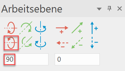
- Rotate the work plane in the X-axis by 90°.

- Start NEW MODEL. (e.g.: "bk1, bracket")

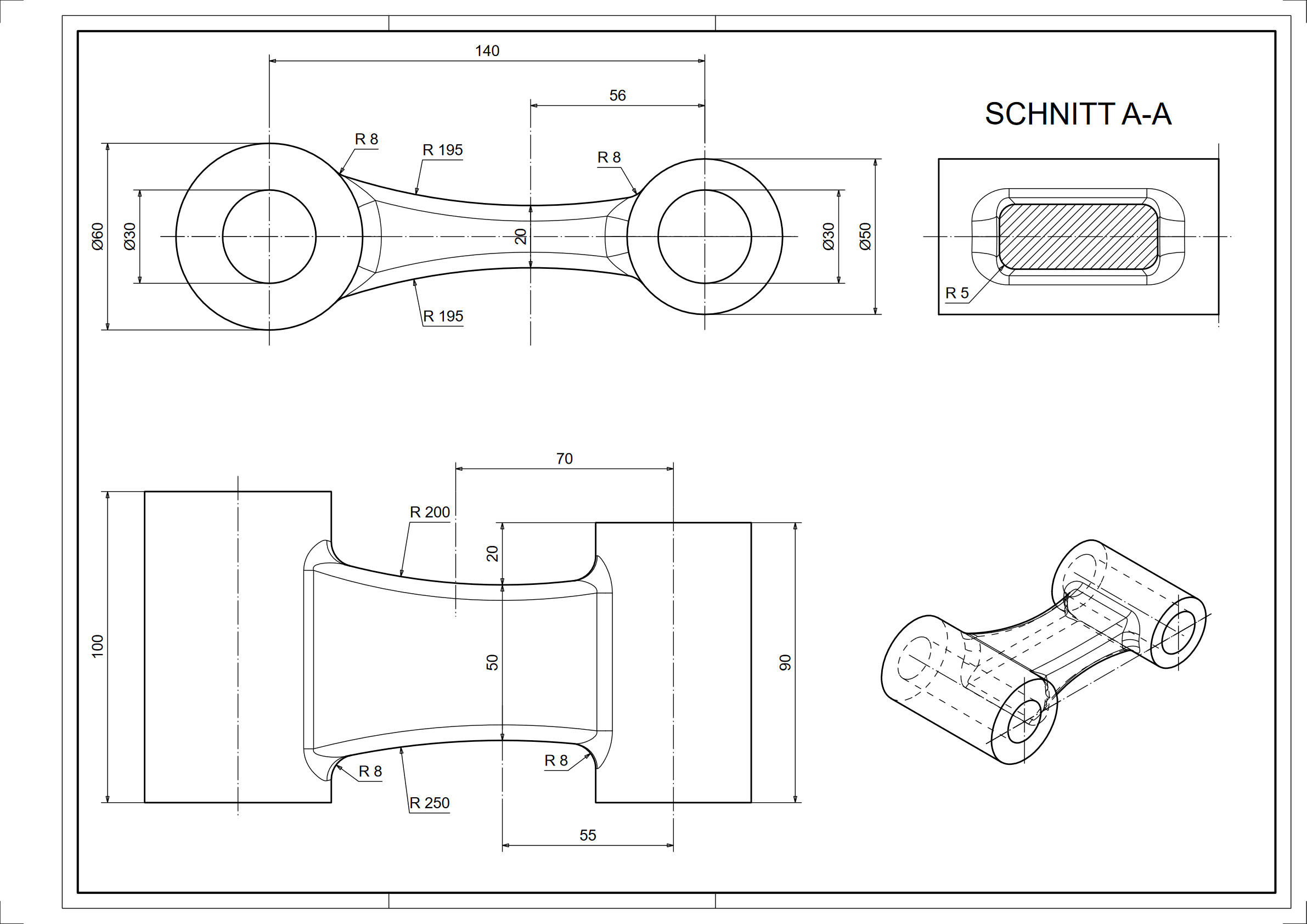
- Draw the first pipe contour. Then define this as a box.
(height 1 = 0; height 2 = 100)

- Start NEW MODEL. (e.g.: "bk2, bracket")
- Draw the second pipe contour. Define this as a box as well.
(height 1 = 0; height 2 = 90)

- Start NEW MODEL. (e.g.: "bk3, bracket")
- Draw the first contour of the object. The contour should protrude into the two tubes.

- Reset the work surface (RESET WORK PLANE) and draw the second object contour. The contour should protrude into the two tubes.

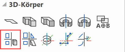
- Select DEFINE 2-VIEWS OBJECT and click on the two outlines drawn previously. The following 3D object is generated!

- Union the three models with the Boolean calculation UNION.


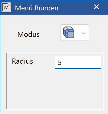
- Select EDGE BLEND, click on the object. Select the BLEND SINGLE EDGE mode, a radius of 5 mm and round the 4 long edges.


- Select EDGE BLEND, click on the object. Select the mode FILLET SUCCESSIVE EDGES, a radius of 8 mm and round the two tubes with the middle part.


- Set the desired dimension and create a new plot.