Chute

Workshop
- Start NEW MODEL (e.g.: "bk, flange1, chute")
- Draw two rectangles [(200 x 200) and (280 x 280)] and put them in the correct position.
Define a box. (height 1 = -10, height 2 = 0)

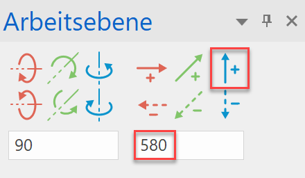
- Move the working plane 580 mm upwards. (CHANGE WORK PLANE)

- Start NEW MODEL (e.g.: "bk, flange2, chute") and draw two more rectangles [(850 x 600) and (930 x 680)].
Define a box. (height 1 = 0; height 2 = 10)

- Select WORK PLANE BY 3 POINTS and snap to the three points using the snap function.


- Start NEW MODEL (e.g. name: „sheet metal 1“) and draw the first side sheet metal.
(This must be a closed contour!).

- Select DEFINE SURFACE. (height = 0) / (colour = 12)

- This plane can now be mirrored on the opposite side using the MIRROR SELECTION. (First reset the WP). Or repeat points 5 - 7 for the second side.
- Repeat points 5 - 7 for the third and fourth sides.

- Set all main dimensions and then derive the plot (see example PEDESTAL, from point 19).
